Aitalmac Co.,LTD
Add: Hengsheng road 001#,Gao Chun
economic development zone.
Nanjing, 211300 P.R. China
Tel: 0086-25-57311800
Fax: 0086-25-57889845
Web: http://www.aitalmac.com
¶ Orbit A5 SawJet user manual
Copyright © 2021 by AitalMAC Co., LTD
In line with our policy of continuing product improvement, specifications and information contained in this manual are subject to change.
¶ Introduction
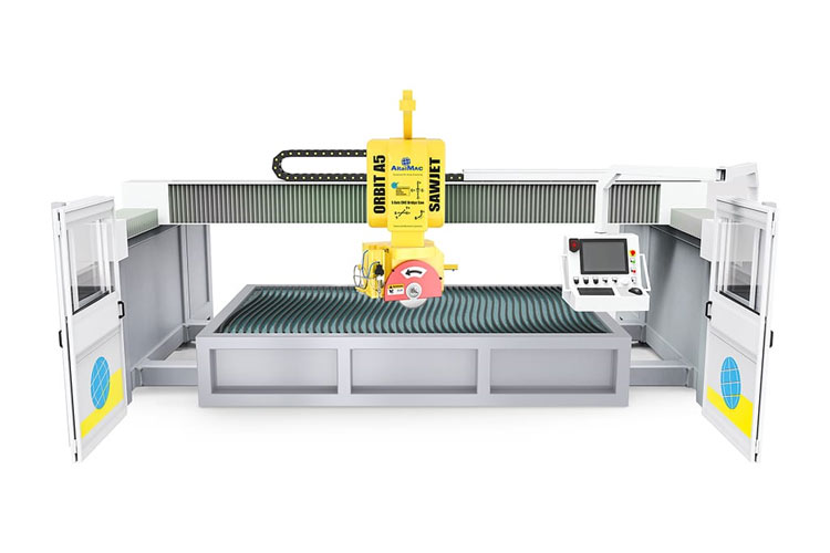
Congratulations, you have just bought an ORBIT A5 SawJet CNC Bridge Saw. The ORBIT A5 SawJet is the latest product of our company. The appearance of the machine is stable and firm, and the sealing of the working space of the machine is safer.
The design of software is simpler, more convenient and more humanized. It is a new integrated software. I/O design let customer be more intuitive about the operation of the machine. When the worker use machine, it is more convenient for users to observe the operation of each part of the state, more convenient troubleshooting.
To facilitate, we, the constructor, have included a manual of our product. We advise you to read this manual carefully, it contains useful information about installation, use and maintenance of your CNC Machine. It will result in longer life and easier use.
¶ General information
¶ Constructor
The company AitalMAC has been constituted by Mr. Romeo Toniolo, which has extensive experience in designing and constructing machines for natural and artificial stone processing. After years of research and development, and repeatedly proving itself reliable with suppliers and trading companies all around the world, AitalMAC has acquired extensive technological know-how and a upstanding reputation which represents the best warranty for AitalMAC’s customers.
¶ General description
ORBIT A5 SawJet is a stone processing CNC Bridge Saw with Waterjet add on
¶ Machine characteristics:
On the model ORBIT A5 SawJet the X and Y rails and the table of the machine is made of welded steel hot galvanized with a final coating of epoxide painting enamel, the upper side of the machine is made of powder coated welded steel.
The X Y1 Y2 Z B C and V axis motors are AC brushless motor close-loop, the Y axis is controlled in gantry by two motors, which are controlled separately, and are homed separately by the controller.
The Main Motor is a direct drive spindle with aluminum frame, it is compact in size but powerful, it has flanges to mount a blade Max Diameter 500mm, and a ½ GAS attachment for drills and bits.
The cable-drag chain and the electric cables used on the mod. ORBIT A5 SawJet is purposely made for a use at high speed, and are resistant to dust and wear and tear. All sensors used on the mod. ORBIT A5 SawJet are watertight.
The power electric box is positioned on the side of the machine; the box is equipped with a 9 axis CNC controller, on the main control panel of the machine there is a monitor with user friendly AitalMAC's software interface.
The water circuit for the cooling of the blade switches on and off automatically, when the machine rotates the B axis to 90 degrees the water will flow to the center of the spindle to enable cutting with drills or bits mounted on the ½ GAS attachment on the spindle.
The machine is optionally provided with an oil pump to lift the table up and down.
The Waterjet add on (either KMT intensifier pump or AitalMAC direct drive pump) at 60000PSI feed the nozzle next to the blade which can tilt separately with the V axis, allowing for 5 axis waterjet cut.
¶ "CE" Certification
The CNC model ORBIT A5 SawJet is designed to operate correctly in an electromagnetic atmosphere of industrial type and is equipped with all the mechanical and electrical safety protections in conformity with the following European CEE rules and regulations:
Directive machines 2006/42/EC
Directive low tension 73/23 CEE
Directive Electro-magnetic compatibility 89/336 CEE - 2004/108 EC
EN ISO 12100-1 : 2003 - EN ISO 12100-2 : 2003 - 89/391/EEC - 89/656/EEC (Machine safety)
EN-60204-1:2006 -EN-60204-11:2000 (Electric equipment safety)
2006/95/EC (Low tension electricity)
CE/108/2004 (Electromagnetic compatibility)
EN-55011 (CEI 110-6) (Limits and methods of measure of characteristics of radio disturb of industrial, scientific and medical apparatuses (ISM)
EN-61000-4-2 / 4-4 / 4-6 (1996)
EN 61800-3 (1996)
Results of all tests make part of the technical dossier; AitalMAC will disclose this documentation only against special request.
The machine is delivered with the CE mark exposed.
¶ Warranty
The warranty of the machine is 1 (one) year from the date of the effective installation by AitalMAC’s or third-party engineers. In case of eventual faults or defects on material or manufacture the customer has to inform the producer or the relevant sale agent about the problem by registered letter immediately. If the complaint is accepted from the producer – he will replace and/or repair the components (the machine or its parts). In the warranty are not included expenses for disassembling, assembling, sending of parts, and expenses regarding the producer’s engineer (food, accommodation, trip). The reparation of the respective component does not mean reopen of the warranty period for the whole machine (only in case of replacing of the machine). The producer is not responsible for damages brought about from customer or third party due to wrong handling with the machine. From the warranty are excluded parts which were accidentally damaged during the transport, during the lifting and placing of the machine, due to wrong connection to the electrical feeding line (these are included if those operations are provided by the producer). From the warranty are excluded components mechanically or atmospherically worn due to insufficient maintenance or unforeseen or forbidden use. The producer is not responsible for not authorized modifications or repairs. The validity of the warranty is subordinated to the corrected execution of the maintenance like described in this manual. For components supplied from third party valid warranties of third party.
This warranty covers only parts of CNC machine with brand Aitalmac sold by Aitalmac and its subsidiaries, affiliates, authorized resellers, or country distributors.
The term "CNC Machine" is limited to the hardware components, does NOT include applications or programs, third party products or devices without the Aitalmac brand.
The warranty period starts from the date of purchase, as indicated from the tax document or other such document.
In order to receive assistance in warranty, it may be required to provide proof of purchase.
To the extent permitted by local law, new machinery and any product or replaced component, may contain new materials or used with equivalent performance and reliability. Any replaced product or part will have same functionality or at least equal to the original product or component replaced. Replacement parts are warranted to be free from defects in materials and workmanship for a period of 6 months if greater than the remainder of the period of warranty of the machine in which they are installed.
If during the warranty period Aitalmac is notified of defects in the machine covered by this warranty, Aitalmac will repair or replace the product, but if Aitalmac requires the defective component to be returned, Aitalmac will have no obligation to repair, replace or refund until the defective part is returned.
In the case of recurring failures of components, Aitalmac at its sole discretion can decide whether to replace the product with one same or equivalent in performance, or refund the purchased price.
¶ Exclusions
This limited warranty does not apply to consumables or to products which have been removed of serial number or have been damaged or rendered defective due to accidents, misuse, intentional misuse, contamination, virus infection, improper maintenance or calibration or inadequate or other external causes;
Also, to software, interface, parts or supplies not provided by Aitalmac, improper preparation or maintenance on the site where the machine is installed, loss or damage in transit, or to modifications or assistance by unauthorized parties.
For CNC machines, the use of tools of third parties does not affect this warranty or any assistance contract with Aitalmac. However, if the fault or defect were attributable to the use of third-party tools, Aitalmac will charge the standard time costs and that of the materials for the intervention.
As a precaution against corruption or loss of data, back up periodically the data stored on hard drivers or other storage devices, AitalMAC is not responsible for damage to or loss of any programs, data, or the restoration of any programs or data other than the factory software from Aitalmac.
¶ Limitations of Warranty / Local Laws
Aitalmac makes no other warranty or condition of any kind, whether express or implied warranties or conditions of merchantability, satisfactory quality, and fitness for a particular purpose. Aitalmac expressly disclaims warranties and conditions not expressly stated in this warranty statement. Any implied warranties imposed by law are limited to the duration of the applicable warranty period.
Some states do not allow time limitation on implied warranties, or the exclusion or limitation of incidental or consequential damages for products intended for the consumer, nor the rights of the consumer. In such states or countries some of the exclusions or limitations in this warranty may not apply to the purchaser.
This warranty is applicable and may be enforced in all countries in which Aitalmac or an authorized service center Aitalmac offer service in warranty, it being understood, however, that the availability of the service and the time of intervention may vary from country to country and may be subject to legislation in the country of purchase. For details contact the service center Aitalmac or an authorized representative.
This limited warranty gives the purchaser specific legal rights, which may vary from state to state and country to country. For exact rights the buyer is obliged to acquaint themselves with the legislation in force in the state or in the country of affiliation.
the warranty terms contained in this statement, except to the extent allowed by law, do not exclude, restrict, or modify but are in addition to the mandatory rights applicable to the sale of this product to the purchaser/final client.
¶ Limitation of Liability
To the extent permitted by law, the remedies provided in this warranty are the sole and exclusive remedies available to the buyer.
These terms and conditions supersede and cancel any prior contract or statements, including those found on sales documentation by Aitalmac or opinions provided on behalf of Aitalmac to the purchaser in relation to the purchase.
To the extent permitted by law, except for the obligations specifically set forth herein, in no event Aitalmac be liable for any damages caused by the product or the failure of the same, including any direct, indirect, special, incidental or consequential damages, whether based on contract, tort, and other legal interpretation and regardless of AitalMAC that has been advised of the possibility of such damages. Aitalmac shall not be liable for any claim of reimbursement made by third parties or made by the purchaser on behalf of third parties.
¶ Software Technical Support
Technical support for the software Aitalmac and third-party software preinstalled by Aitalmac is available at Aitalmac using different contact methods, including electronic media and telephone, for five years from the date of purchase.
How to contact Aitalmac:
In case of need for warranty service or technical support during the warranty period, contact your local assistance AitalMAC. The addresses found at: http://www.aitalmac.com.
When you call AitalMAC or an authorized service center AitalMAC you must have available model name and serial number of the product, any error messages and the type of operating system.
After reading the user manual and maintenance!
¶ Settlement of customer’s expenses
On the base of documentation by constructor (if there is no another agreement between customer and constructor) customer has to provide on his expenses following:
- Preparation of the hall – basement, drainage (see Placing),
- Water supply in conformity of norms in the country of use, (see Water Connection),
- Supply of electricity in conformity of norms in the country of use, (see Electricity)
- #00/#000 Grease for automatic grease pump, and hydraulic oil for the waterjet system and tilting table if the option was acquired.
¶ Assistance center
AitalMAC's CNC machines can get service ONLINE.
AitalMAC has its primary assistance center in its residence, and other centers distributed around the world. For every help or information contact sale agents of AitalMAC in your country to ensure the assistance center which is close to you, or contact directly the head office of AitalMAC Company. Agents will help you detect and solve all problems; retailer or constructor will require dates of product marked on the label on the machine.
If the machine needs the intervention of a technician, Aitalmac can provide the technical staff that might be prepared personal of the dealer or distributor or authorized third parties.
The machine has no parts that are not replaceable by the customer himself, all parts are easy to replace.
Aitalmac does not consider correct for anyone in the distribution network, to add costs to the machine sales value, for assistance services.
Aitalmac considers proper to assist with technical staff if required, but for a fee, during or out of warranty.
¶ About manual
The Customer must read with extreme attention all information written in this manual. Exhaustive study of manual, preparation, installation and right use of the machine constitute the base of the good relationship between constructor and producer.
¶ Purpose of the manual
The purpose of the manual is to give the customer all necessary information so that he would be able to install and work with the machine by his own in the most independent and sure way. It comprises inherent technical information, information about function of the machine, security and maintenance.
NOTE: Before starting of whichever operation on the machine the customer must read carefully contained instructions in this manual. In case of any doubts on the corrected interpretation the constructor must contact producer or sale agent for necessary clarifications.
¶ Addressees of the manual
The manual is appointed to the operator of the machine and to the customer’s technician as well. The customer must explain carefully function of the product to both of them.
NOTE: The constructor is not responsible for any of damages eventuate from insufficient perusing of this manual.
¶ Conservation of the manual
The manual is not printed but is saved in the CNC computer; the manual must be conserved in the machine. It is recommended to make another copy of this manual (with attachments) and keep it in a safe place in office.
NOTE: The machine does not have to be yielded to third party without informing the constructor. (The constructor must verify that the machine respects all norms in the country of use at the moment of the cession in case of incident. All parties, which have contracted the machine, are incumbent in pecuniary penalty).
¶ Installation
¶ Transport and store
While transporting the machine beware:
- The machine axes are all locked and cannot move.
- The machine is always straight loaded,
- The carriage is blocked (you can use strings),
- The machine is standing always on a dry place,
- The machine is nailed with steel to the floor so it cannot move.
While lifting the machine beware:
- Your lifting equipment is supporting 8000 kg,
- You are using only the lifting points,
- When the strings are tight you will not damage any part of the machine.
- Use forklift truck, from the side only when extracting machine from the container.
- When using a forklift truck, see if the machine rests straight while lifting.
While storing the machine beware:
- The machine is stored on a dry and clean place.
- All the guides and the moving parts are greased with a special grease to store metal parts.
- Do not store the machine outside.
¶ Lifting and handling
Place container on the floor, remove the turnbuckles fixing the machine to the container, lift the back of the machine with provided hydraulic jack and install wheels on the back of the machine, and extract the machine from the container using a forklift (8Ton at least) till the machine is out enough to be lifted with a crane
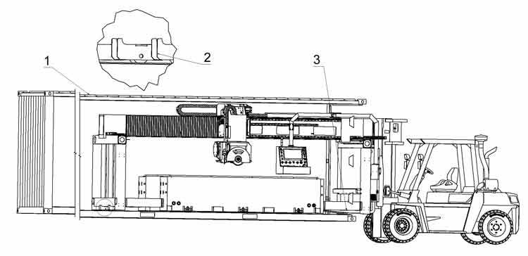
- Place container on the floor.
- Insert wheels on both sides in the back.
- Use wheels in the back and forklift in the front.
pull out machine enough so it can be lifted with a crane.
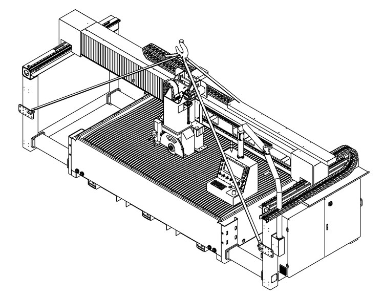
Use the appropriate hooks and holes to lift the machine with appropriate crane, be sure that your lifting belt or chain can hold the weight and see if the machine rests straight while lifting.
¶ Machine Installation Leveling
Read the placing chapter of this manual for correct placement information.
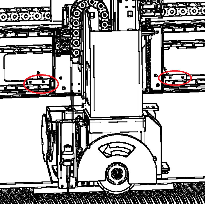
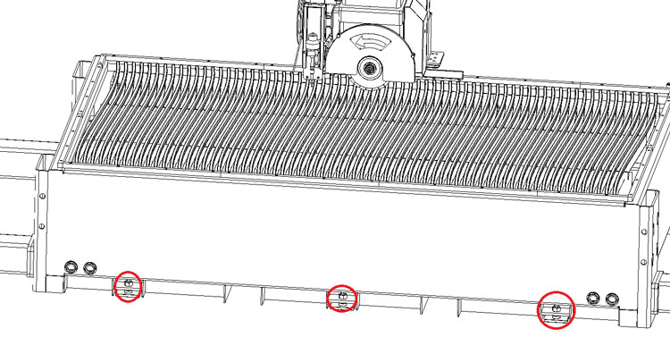
Remove the Y axis locking brackets, and locking screws on both sides you used to lift the machine.
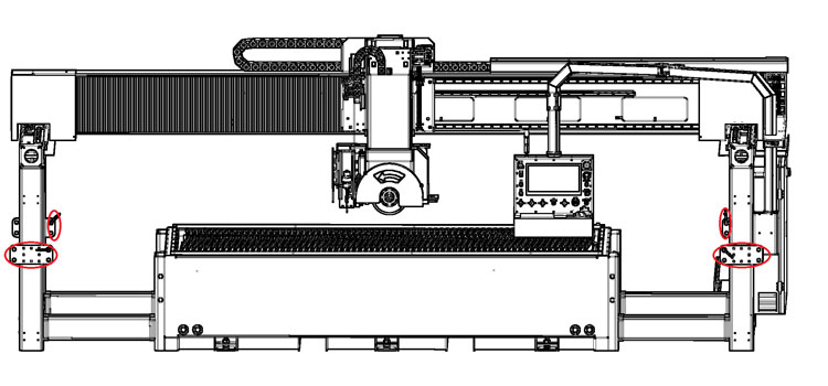
Remove the X and Y axis RED shipping fixtures
Remove the brackets that hold the control panel on the bridge.
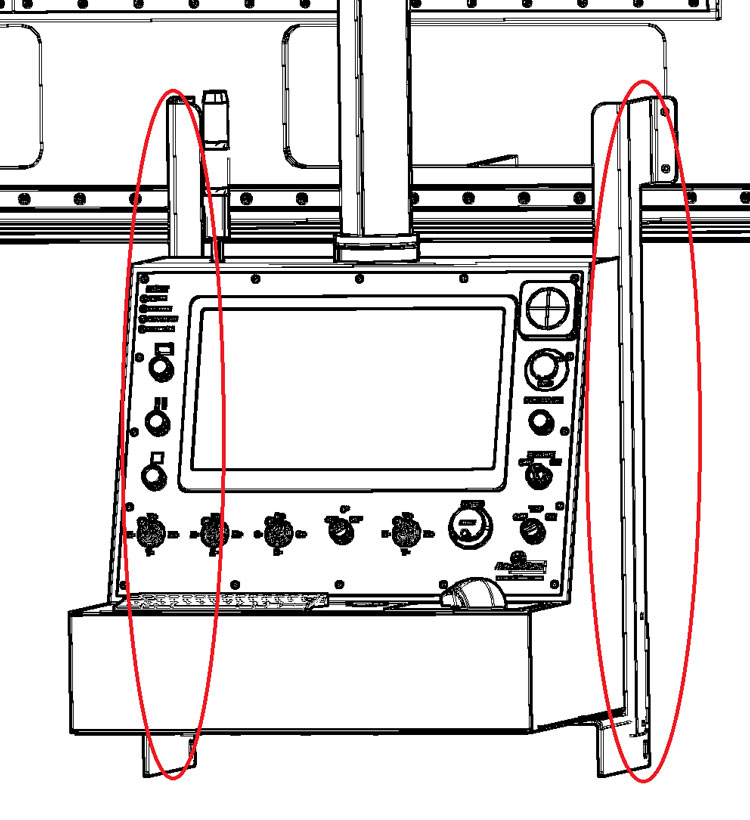
Install the safety bolts to prevent the arm of the control to enter the working area.
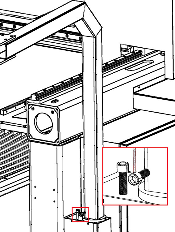
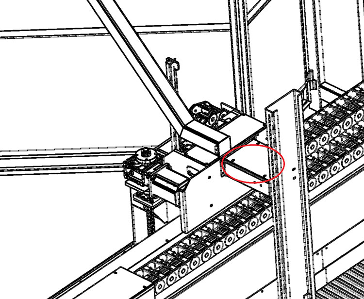
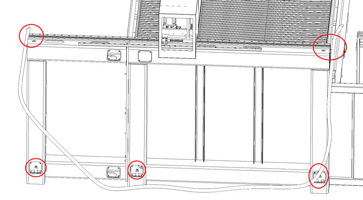
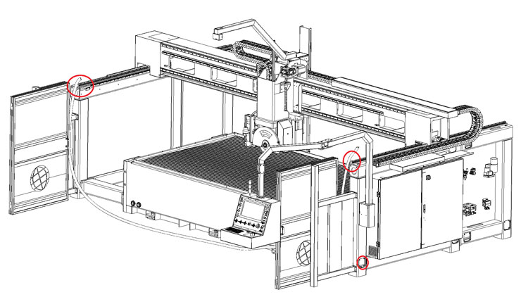
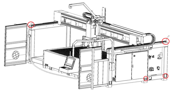
Fit the back frame on both sides of the machine, and make sure line up the linear rails and the racks.
On the right side pass all the cables trough, and plug them up.
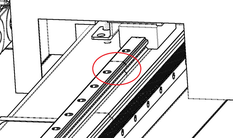
While lining up the rails make sure the taper alignment pin fit properly, hammer them in after lining up and before completely tightening the bolts
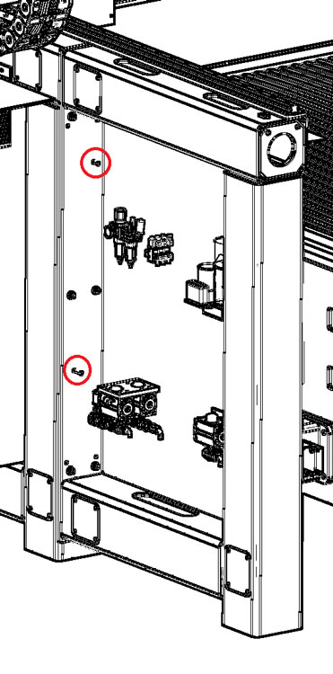
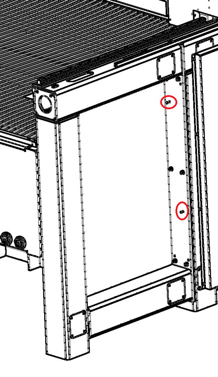
Tighten bolts to securely assemble the back side of the Y rails.
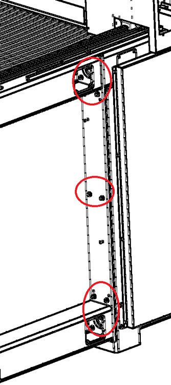
Pay particular attention to the joint of the Y rails on each side while tightening the Y rails, there must be a smooth transition between the two parts of the rail
Install the door, frame in front of the machine, and the camera arm.
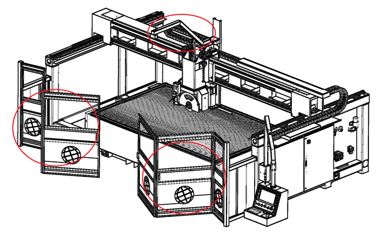
Make sure to plug the camera USB cable into the small SBC in the box behind the camera arm.
Check the highest rail side of the machine, keep that point as reference and use water level tube to level the machine, start by level Y rail with highest point, use hydraulic jack to help you lift machine if needed, Adjust the level of the machine by adjusting the screws inside the machine feet.
Level the opposite side, but keeping the reference level from the side already levelled
Tighten the center feet front and back of the table, and check all levels again, keeping the same reference side.
Double check the level, make sure all machine feet touch the floor, also check again the Y rail joint smooth alignment.
Assemble the other covers and bellows, connect all waterjet joints, use blue goop on waterjet threads.
Connect electrical power, details in electricity chapter
Connect water, details in water chapter
Then power on the machine, details in put to use chapter.
If you encounter problems please check attached troubleshooting.
Machine is now leveled and safe to operate to work with, please refer to the CNC and CAM software manuals to learn how to program the machine.
¶ Electricity
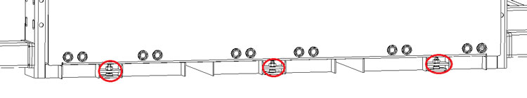
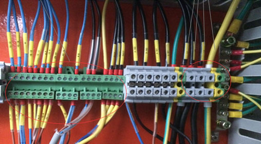
Find and plug all the green plugs for power, make sure the cables on the bottom and top plugs are numbered the same.
The main power supply needs to be hooked up to L1 L2 L3 and ground, and only for 380V machines also the Neutral, please look at machine name plate for Voltage and Wattage to calculate proper cable size.
Connect the 3 phases L1 L2 L3, and the ground (PE green/yellow), and Neutral blue N only for 380V machines.
If for any reason you need to replace the cable of the machine, make sure the supply cable it’s the same size or bigger than the one supplied.
Check power input to be from 220V or 380V ±10% depending on name plate of machine.
Always check the machine label to calculate proper amperage of machine to mount proper safety devices according to regional regulations, please trust label printed Voltage and Kw over this manual.
Before connecting the supply cable check that the main switch in electrical box is OFF and main supply is OFF.
The power source must have a residual current device according to local security law (normally 0,03 Ampere)
It is recommended to connect the machine to a separated ground, such as a 20mm ground rod into the ground.
ATTENTION: If oil pump does not function properly even though it has been filled with oil, it is necessary to invert two of three cables of phases.
ATTENTION: Only the electricians can open the box and execute maneuvers or repairs
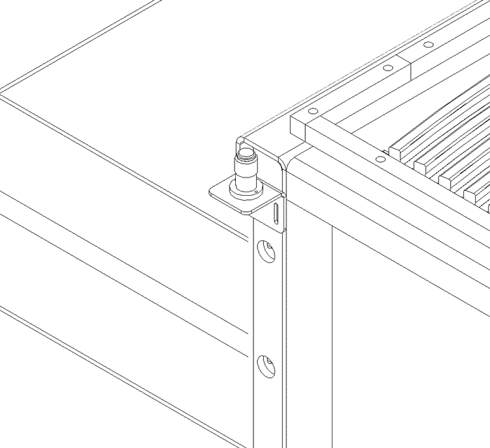
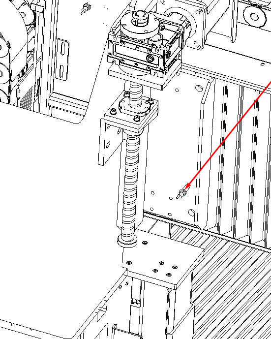
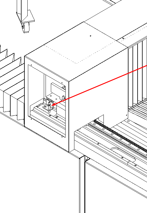
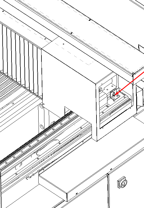
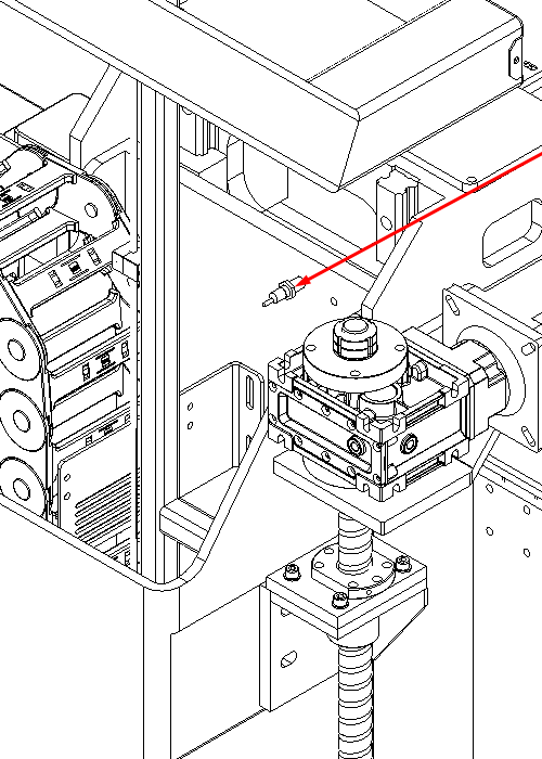
¶ Mount the probe
Mount the probe on the back right side of the table, the screws are already in the holes to fix the probe, but the probe is unmounted and will be found in separate wrapping, keep the probe top level slightly lower than the table rubber table, plug the cable wire should be zip tied nearby.
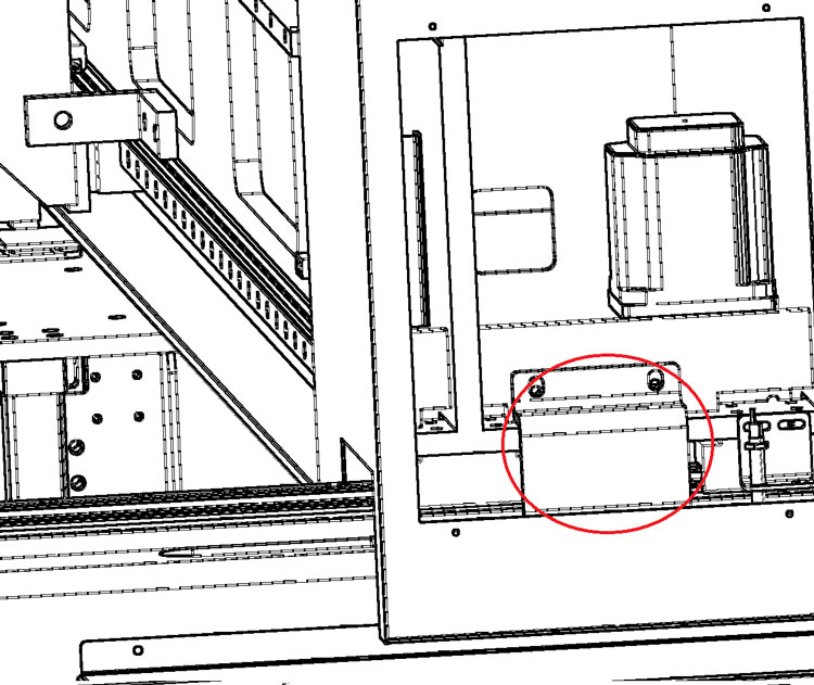
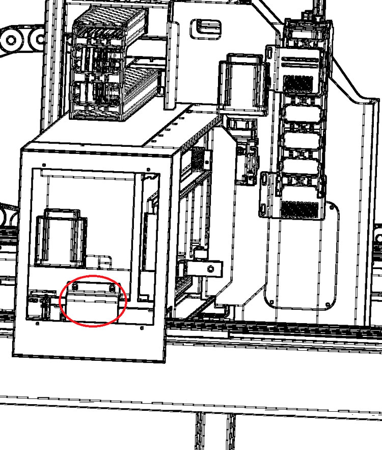
¶ Hydraulic Pump and Oil
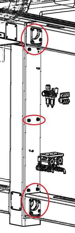
The Hydraulic pump is situated on the right side of the machine in auxiliary box.
Open the door of auxiliary box, which is next to electrical box, you will see it.
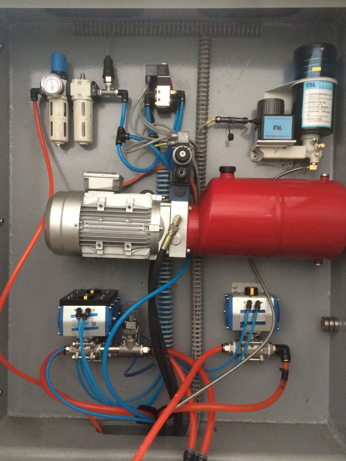
Find the hydraulic pipes from inside the machine frame, and pull them to the pump, there are only two hydraulic pipes, there is visible black tape to show the proper order of the pipes.
Remove the top plugs, and fill the pump with oil Hydraulic oil 46 (not supplied with machine), the plug has a level gauge, use it to fill the pump properly; do not fill the pump completely full.
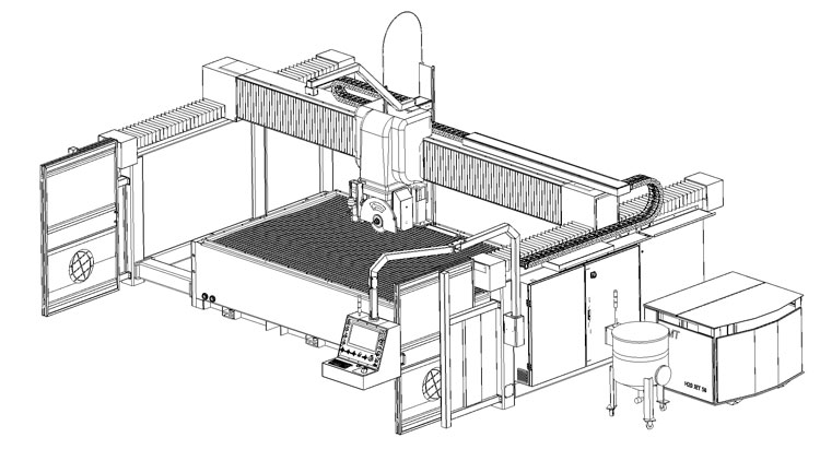
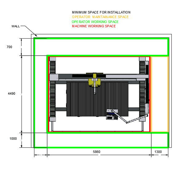
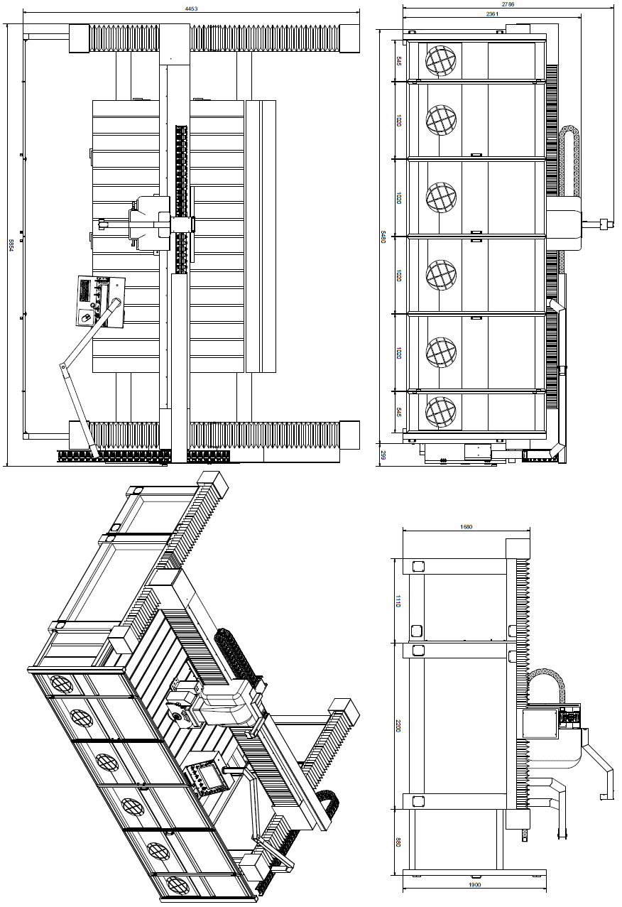
¶ Placing + environmental conditions
The machine does not demand particular environmental conditions. It must be installed indoor – in production hall. The hall has to be illuminated, ventilated and provided with flat concrete pavement. To place the “ORBIT A5 SawJet” study the designs 2.3.A. and 2.3.B., make sure that the electrical box door can be opened to do maintenance.
Control if the “ORBIT A5 SawJet” is not moving while working..
The minimum temperature of the hall does not have to be less than 4/5 °C (40 F); the maximum temperature does not have to exceed 40 °C (104 F).
NOTE: Never expose the machine to direct solar beams. If the temperatures exceed the standards contact the technical service.
¶ Lighting system
The lighting system in production hall must respect the norms EN 12464 the lighting of workplaces or ISO 8955 the customer needs to make the light night system for the machine at norms. It has to provide good visibility in every part of the machine. It must eliminate reflections, which would be dangerous during operating. The lighting system has to ensure good visibility of the display and the emergency button.
On special demand the working zone can be equipped with one ulterior source of light.
¶ Vibrations
In consistent and correct way using of the machine, vibrations are not in such levels to create dangerous situations.
¶ Sonorous emissions
The machine is designed to avoid or reduce the level of sonorous emission maximally. The level of emitted acoustic emission in the workplace does not exceed 85 dB. The measured value for the machine is 83.9 dB and declaration constant K = 4 dB.
NOTE: values of indicated noisiness are levels of emission and they do not represent real operating levels necessarily.
¶ Water Connection
The machine main water supply is located in the auxiliary box of the machine.
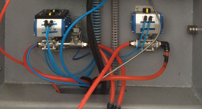
Make sure your connections are in conformity with the local laws of security.
The valve on the right it's for the sprinkles to wash the parts on the table, the water can be clean tap water or recycled 5~10 microns
The left front valve it's for trough spindle water, here clean tap water is recommended.
The left back valve it's for blade water, recycle water is recommended here as long as the water doesn't contain big particles like wood splinters and such.
Connect the water directly to the water valves in auxiliary box of the “ORBIT A5 SawJet”.
The thread on all valves is a half inch NPT female thread.
Water pressure: minimum 2 bar, maximum 4 bars.
¶ Sensor placement
This is an explanation of where all the homing sensors on the machine are located
Joint0 X Sensor (remove cover on the head to access)
Joint1 Y1 Sensor (on the left side of the machine)
Joint7 Y2 Sensor (on the right side of the machine)
Joint2 Z Sensor (remove cover on the head to access)
Joint3 B Sensor (behind the blade)
Joint4 C Sensor (remove cover on the head to access)
¶ Put to use
¶ Preliminary controls
Installation and the first start of the machine have to be tracked or executed from AitalMAC technician. In the best way the technician of AitalMAC should collaborate with the technician of the customer who will have therefore possibility to acquire a maximum of information for working with the machine and maintenance subsequently. Before putting in the function it is necessary to make following checks to avoid errors or incidents during the starting of the machine:
- Check if the machine is not damaged after shipment or placement,
- Check (with a multi-tester) interconnection between the electrical box, control panel and other connections,
- Check connections of all external sources (water, electricity), check for leaks,
- Check the free movement and eventual free spin of all mobile parts of the machine.
- Make sure all axis can move and move in the right direction like indication on machine, contact factory if machine moves wrong.
- Check the correct function of all the sensors, all sensor are proximity sensors, use a metallic object and place it in front of the sensor to trip it, see in the machine CNC manual interface when the sensor trip in the I/O page it will be displayed clearly. Contact factory if sensors are not tripping.
Turn the main-switch turn the “enable key” (5) on and push the “power” button (2). If the power button does not light, please check fuses inside electric panel.
Also, power on the PC, and double click on the Orbit A5 SawJet shortcut on the desktop to open the machine control program.
Press the switch on button on the interface

if you are not able to move the machine and you are welcome by a “Joint0 on limit switch” error message, is because one of the limit sensors is on the limit, Joint0 will be X, Joint1 Y and Joint2 Z, Joint 3 is B, Joint 4 is C, and Joint 7 is Y2, to move the machine out of the limit, simply click the override limits check in JOINT part of manual page, then press switch on button on software interface
you will now be able to move the machine out of the limit, by clicking on the Joint tab and choose the axis in limit from the drop down list and moving over with the MOVE+ or the MOVE- buttons.
¶ Description of the control board
 |
(1) Screen/Monitor/Display of the machine |
 |
(2) POWER BUTTON has two functions, first function is to power on the machine when enable key is on, the second function is the power on button of the CNC controller, CNC controller power button functions the same as a computer power button, if you press twice too quickly then it won't power on, if you hold for 6 seconds CNC controller will shut down, this functions persists whether the key is on or off or the POW. ON button light is on or off. |
 |
(3) EMERGENCY STOP for stop the machine in emergency cases (on the control panel) |
 |
(4) General switch I\O selector for turn on and off the machine from the electric panel, it's recommended to turn off the PC and controller before turning the General switch off, you can only open the electrical cabinet door if the switch is on the off position |
 |
(5) Enable Key, to enable and disable machine motion, turning this key to the left (off) will turn off the machine and the power on button, and you will not be able to switch on the power until the key is to the right (on) |
 |
(6) TCP toggle, to enable and disable machine tool center point motion, with this toggle to the left (off) the machine motion will be relative to each singular axis not effected by the rotational axis, with the toggle to the right (on) the machine motion will be relative to the tool cutting direction, this kind of motion is effected by the rotational axis |
 |
(7) AUTOMATIC BUTTON for starting the automatic functions |
 |
(8) PAUSE BUTTON for enter suspend state. |
 |
(9) STOP BUTTON for stop automatic functions |
 |
(10) Speed control wheel for the movement of all axis |
 |
(11) Angle toggle of B and C rotational axis, there are three angles of choice: 0° the rotation is free 45° rotation is in 45° increments 90° rotation is in 90° increments |
 |
(12) I/O button for panel computer |
¶ Starting the machine
Make sure the General switch is on (4), release the emergency stop (3), turn the enable key to the right on (5), press POW. ON button once (2), press the I/O to power on the panel computer (12), wait for red light to go on (about 2 minutes), then open the Machine Application.
If the machine fails to boot visit boot fail and connect for more details
Click the switch on button on interface
wait till the interface is completely enabled to start working
¶ Working with the machine
The operator of the machine must have pre knowledge of a CAD program, the operator must read carefully and understand the CAM and CNC programs manuals, and watch carefully the video tutorials.
The machine was designed and constructed to cut kitchen tops and vanity tops, to do this it’s necessary to design the shape of the sink in a CAD program and save it as a DXF file (a CAD program is provided in the machine PC), then import the DXF in the CAM program, and setup the blade cuts to cut out your designed parts, then post-process the cuts g-code.
After starting the machine, use parking button to park the machine, and use the table up and down buttons in manual page under table tab to lift table and load the stone, then lower the table, from the automatic page in the machine program load and start the start the g-code to let the machine cut the stone automatically.
The stone can alternatively be cut with manual operations from the machine application, or with simple X and Y cutting pages also in the machine application to cut simple strips.
¶ Stopping the machine
¶ Stopping the machine during automatic process
Press the Esc button on your keyboard to stop the machine (this will only work if the machine program is active).
Press the stop button on interface.
Press red stop button on the panel (9).
In case of emergency push the emergency button (3)
¶ Stopping the machine when finish working
To stop the machine, use the enable key (5) then close taps (water and air supply). Then shut down the PC. If there is a risk that ambient temperature will go under 5°C (40 F) it is recommended to leave the machine on to avoid damage of electronic cards.
¶ Manually change tool on machine
To manually change blade tool please unfasten the knobs holding the cover for the blade, and take off the cover.

Then use the two provided spanners to unfasten the nut (counterclockwise)

Once the nut is unfastened, pull out the flange and the blade, and load the new blade, the blade mounting shaft diameter is 50mm, once the new blade is loaded, put back the flange, fasten back the nut, and mount the cover and lock it with its knobs.
¶ Interpretation of terms
¶ Main switch
The main switch on the electrical box has to be switched on to start the ORBIT A5 SawJet. You must power off the switch in order to open the door of the electrical box.
¶ Control panel

The control panel with his monitor is the operator interface with the machine, provided with Pegasus and ORBIT A5 SawJet programs.
On the panel there is also an emergency button, to press in case of emergencies, the machine enable key, and the power on button of the machine, on top of the emergency there is the power on button for the panel computer, and on top of the screen you can find the status lights. On left of the screen there are three colors of buttons. The green button is automatic button. The yellow button makes the machine enter suspend state. The red button is used to stop. There are also controls at the bottom of the screen. The angle toggle of B axis knob is in the center. Speed control button is on the left of TCP toggle.
¶ Head

The head of the machine is the central part of the machine, the up and down movement of the head is the Z axis, the back-and-forth movement is called Y axis, and the spinning of the head around Z is called C axis, the inclination of the blade up to 90 degrees is called B axis.
On the machine head is mounted the spindle or main/blade motor, on which the diamond blade is mounted to cut stone.
¶ Table

The table is in welded steel, but it will be covered in either wood cement or rubbers or plastic materials according to customer discretion, the table can be lifted up to allow easy loading of the stone slab.
¶ Electrical box

The electrical box is mounted in the right side of the machine, inside you can find all electrical components of the machine, inside you will find also the 9 axis CNC controller, you should keep the door locked, and open only after properly powering off the machine from the main switch.
¶ Auxiliary box

The auxiliary box is next to the electrical box. The auxiliary box has hydraulic pump, water connection, air pressure meter, the lubrication system and so on. Some auxiliary equipment of the machine is inside.
¶ Bridge or X bridge

The bridge of the machine is supported by the shoulders, the head of the machine slides to the left and right on the bridge, this movement is called X axis which is controlled by joint 0 motor.
¶ Y rails, or Y ways

The Y rails are located up the two sides of the machine, and on the shoulders of the machine slide forward to backward, creating the Y axis movement.
¶ Feet

The feet of the machine are the parts that sit on the floor. The machine has six feet. There is a screw inside each foot that can adjust the height of the foot. When the machine is on the ground, the feet height need to be adjusted to make the machine levelled and stable.
¶ 9 Axis CNC controller
The 9 Axis CNC controller is located inside the electrical box, it controls the whole machine, the control panel interface connects to the CNC controller to get control of the machine.

¶ Lubrication
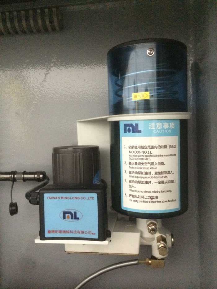
Use a grease pump to fill the grease system with #00 or #000 grease and machine will pump grease regularly when spindle is on. The machine program has settings for the grease pump frequency. Caution Labels are attached to the grease lubrication system. Please read it carefully.
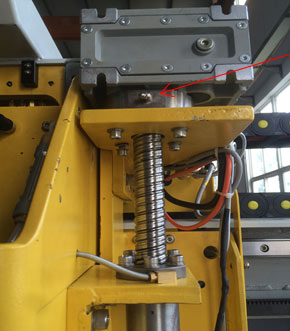
The automatic grease pump takes care of most lubrication but not all, operator still needs to manually pump grease in the Z bearings once a year, also the table hinges, and the racks of X and Y axis.
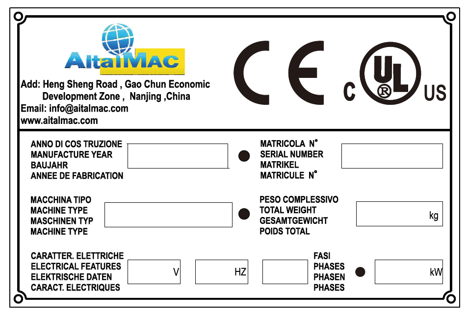
¶ Label
The label with data regarding the machine is situated on the right side of the ORBIT A5 SawJet, on the top of the electrical box. There are marked data which producer will ask for in case of complaint.
¶ Operation
The ORBIT A5 SawJet can be operated from the CNC only in Manual or Simple linear cut mode, or it needs to be programmed i to process fully automatic job. The CAD (DraftSight or any CAD) is used to draw the shapes the machine has to work. The CAM (AitekCAM or any other CAM with appropriate post processor) is used to program the cuts on the CAD shapes, and saves them as g-code. The CNC program is used to play this g-code on the machine, the CNC program can also move the machine in manual, or start simple linear cuts.
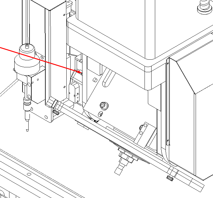
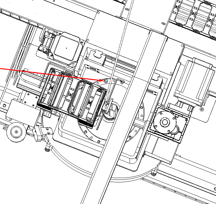
Parts on the ORBIT A5 SawJet sit on the machine table; the parts are located on the table either by measuring off the table and use the table in the CAM as reference, or by acquiring the location with the laser pointer on the machine. Optionally the machine can be mounted with a camera that will photograph the parts and display their location in the CAM interface.