Aitalmac Co.,LTD
Add: Hengsheng road 001#,Gao Chun
economic development zone.
Nanjing, 211300 P.R. China
Tel: 0086-25-57311800
Fax: 0086-25-57889845
Web: http://www.aitalmac.com
¶ Orbit A5 SawJet руководство пользователя
Copyright © 2021 by AitalMAC Co., LTD
В соответствии с нашей политикой постоянного совершенствования продукции технические характеристики и информация, содержащиеся в данном руководстве, могут быть изменены.
¶ Введение
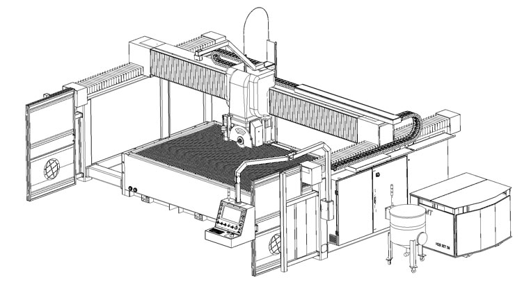
Поздравляем, вы только что купили мостовую пилу с ЧПУ ORBIT A5 SawJet. ORBIT A5 SawJet — новейший продукт нашей компании. Внешний вид машины стабильный и прочный, а организация рабочего пространства машины более безопасна.
Дизайн софта проще, удобен и интуитивен. Это новое интегрированное программное обеспечение. Конструкция ввода-вывода позволяет покупателю более интуитивно понимать работу машины. Когда рабочий использует машину, пользователям удобнее наблюдать за работой каждой части состояния, более удобно устранять неполадки.
Для облегчения мы, конструкторы, включили руководство по нашему изделию. Мы советуем вам внимательно прочитать это руководство, оно содержит полезную информацию об установке, использовании и обслуживании вашего станка с ЧПУ. Это продлит срок службы и упростит использование.
¶ Главная Информация
¶ Конструктор
Компания AitalMAC была основана г-ном Ромео Тониоло, который имеет большой опыт в разработке и производстве машин для обработки натурального и искусственного камня. После многих лет исследований и разработок, неоднократно подтверждая свою надежность в отношениях с поставщиками и торговыми компаниями по всему миру, AitalMAC приобрел обширные технологические ноу-хау и безупречную репутацию, которая представляет собой наилучшую гарантию для клиентов AitalMA
¶ Общее описание
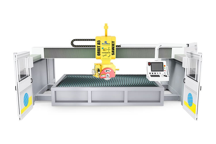
ORBIT A5 SawJet — это мостовая пила с ЧПУ для обработки камня с опцией Waterjet.
¶ Характеристики машины:
На модели ORBIT A5 SawJet направляющие X и Y, а также стол станка изготовлены из сварной стали, оцинкованной горячим способом с окончательным покрытием эпоксидной красящей эмалью, верхняя часть станка изготовлена из сварной стали с порошковым покрытием. Двигатели оси X, Y1, Y2, Z, B, C и V представляют собой бесщеточный двигатель переменного тока с замкнутым контуром, ось Y управляется на портале двумя двигателями, которые управляются отдельно и управляются отдельно контроллером. Главный двигатель представляет собой шпиндель с прямым приводом с алюминиевой рамой, он компактный по размеру, но мощный, имеет флянцы для установки диска с максимальным диаметром 500 мм и насадку ½ GAS для сверл и фрез. ORBIT A5 SawJet специально разработан для использования на высоких скоростях и устойчив к пыли и износу. Все датчики, используемые в моде. ORBIT A5 SawJet водонепроницаемы. Блок питания расположен сбоку станка; бокс оснащен 9-ти осевым ЧПУ контроллером, на главной панели управления станка находится монитор с удобным программным интерфейсом AitalMAC. Водяной контур для охлаждения лезвия включается и выключается автоматически при вращении станка ось B на 90 градусов, вода будет течь к центру шпинделя, чтобы можно было резать сверлами или фрезами, установленными на насадке ½ GAS на шпинделе. Станок дополнительно оснащен масляным насосом для подъема стола. Добавление гидроабразивной резки (либо насос-усилитель KMT, либо насос с прямым приводом AitalMAC) при давлении 60000 PSI на квадратный дюйм питает сопло рядом с диском, которое может наклоняться отдельно по оси V, что позволяет выполнять гидроабразивную резку по 5 осям.
¶ "CE" Сертификаты
Модель с ЧПУ ORBIT A5 SawJet предназначена для правильной работы в электромагнитной атмосфере промышленного типа и оснащена всеми механическими и электрическими средствами защиты в соответствии со следующими европейскими правилами и нормами CEE:
Директива по машинам 2006/42/EC
Директива по низкому напряжению 73/23 CE
Директива Электромагнитная совместимость 89/336 CEE - 2004/108 EC
EN ISO 12100-1 : 2003 - EN ISO 12100-2 : 2003 - 89/391/EEC - 89/656 /EEC (безопасность машин)
EN-60204-1:2006 -EN-60204-11:2000 (безопасность электрооборудования)
2006/95/EC (электроэнергия низкого напряжения)
CE/108/2004 (электромагнитная совместимость)
EN-55011 (CEI 110-6) (Пределы и методы измерения характеристик радиопомех промышленного, научного и медицинского оборудования (ISM)
EN-61000-4-2 / 4-4 / 4-6 (1996)
EN 61800 -3 (1996)
Результаты всех испытаний входят в техническое досье; AitalMAC раскрывает эту документацию только по специальному запросу. Машина поставляется с открытой маркировкой CE.
¶ Гарантия
Гарантия на машину составляет 1 (один) год с даты фактической установки инженерами AitalMAC или сторонними инженерами. В случае возможных дефектов или дефектов материала или изготовления покупатель должен немедленно сообщить о проблеме производителю или соответствующему торговому агенту заказным письмом. Если претензия от производителя принята – он заменит и/или отремонтирует комплектующие (машину или ее части). В гарантию не включены расходы на разборку, сборку, пересылку деталей, а также расходы на инженера производителя (питание, проживание, проезд). Ремонт соответствующего компонента не означает продление гарантийного срока на всю машину (только в случае замены машины). Производитель не несет ответственности за ущерб, причиненный покупателем или третьей стороной из-за неправильного обращения с машиной. Из гарантии исключаются детали, которые были случайно повреждены при транспортировке, при подъеме и установке машины из-за неправильного подключения к питающей сети (включены, если эти операции предусмотрены производителем). Гарантия не распространяется на компоненты, изношенные механически или под воздействием атмосферы из-за недостаточного технического обслуживания или непредвиденного или запрещенного использования. Производитель не несет ответственности за несанкционированные модификации или ремонт. Срок действия гарантии зависит от правильного выполнения технического обслуживания, как описано в данном руководстве. Для компонентов, поставляемых третьими лицами, действуют гарантии третьих лиц. Настоящая гарантия распространяется только на детали станков с ЧПУ марки Aitalmac, продаваемых Aitalmac и его дочерними компаниями, филиалами, авторизованными торговыми посредниками или дистрибьюторами в стране. Термин «станок с ЧПУ» ограничивается аппаратным обеспечением. компонентов, НЕ включает приложения или программы, сторонние продукты или устройства без торговой марки Aitalmac. Гарантийный срок начинается с даты покупки, как указано в налоговом документе или другом подобном документе. Чтобы получить помощь по гарантии, он может необходимо предоставить подтверждение покупки. В пределах, разрешенных местным законодательством, новое оборудование и любой продукт или замененный компонент могут содержать новые материалы или использоваться с эквивалентными характеристиками и надежностью. Любой замененный продукт или деталь будет иметь ту же функциональность или, по крайней мере, такую же, как у оригинального продукта или замененного компонента. На запасные части распространяется гарантия отсутствия дефектов материалов и изготовления в течение 6 месяцев, если это больше, чем оставшийся гарантийный период машины, на которой они установлены. машина, на которую распространяется настоящая гарантия, Aitalmac отремонтирует или заменит продукт, но если Aitalmac потребует вернуть дефектный компонент, Aitalmac не будет иметь никаких обязательств по ремонту, замене или возврату средств до тех пор, пока дефектная деталь не будет возвращена. В случае повторяющихся отказов компонентов, Aitalmac по своему усмотрению может принять решение о замене продукта на такой же или эквивалентный по характеристикам, либо возместить приобретенную цену.
¶ Исключения
Настоящая ограниченная гарантия не распространяется на расходные материалы или продукты, серийный номер которых был удален или которые были повреждены или признаны дефектными в результате несчастных случаев, неправильного использования, преднамеренного неправильного использования, загрязнения, вирусной инфекции, неправильного обслуживания или калибровки, неадекватных или других внешних причин; Кроме того, к программному обеспечению, интерфейсу, деталям или расходным материалам, не предоставленным Aitalmac, ненадлежащей подготовке или техническому обслуживанию на месте, где установлена машина, потере или повреждению при транспортировке, а также к модификациям или помощи со стороны неуполномоченных лиц. Для станков с ЧПУ использование инструменты третьих лиц не влияет на эту гарантию или договор о помощи с Aitalmac. Однако, если неисправность или дефект были связаны с использованием сторонних инструментов, Aitalmac взимает стандартную стоимость времени и материалов для вмешательства. В качестве меры предосторожности против повреждения или потери данных периодически делайте резервную копию сохраненных данных. на жестких драйверах или других устройствах хранения данных, AitalMAC не несет ответственности за повреждение или потерю каких-либо программ, данных или восстановление каких-либо программ или данных, кроме заводского программного обеспечения от Aitalmac.
¶ Ограничения гарантии / местные законы
Aitalmac не дает никаких других гарантий или условий любого рода, будь то явные или подразумеваемые гарантии или условия товарной пригодности, удовлетворительного качества и пригодности для определенной цели. Aitalmac прямо отказывается от гарантий и условий, прямо не указанных в данном гарантийном заявлении. Любые подразумеваемые гарантии, установленные законом, ограничены продолжительностью применимого гарантийного периода. В некоторых штатах не допускается ограничение по времени подразумеваемых гарантий или исключение или ограничение случайных или косвенных убытков для продуктов, предназначенных для потребителя, а также прав потребитель. В таких штатах или странах некоторые исключения или ограничения настоящей гарантии могут не применяться к покупателю. Эта гарантия применима и может применяться во всех странах, в которых Aitalmac или авторизованный сервисный центр Aitalmac предлагает гарантийное обслуживание, при этом понимается, однако доступность услуги и время вмешательства могут варьироваться в зависимости от страны и могут регулироваться законодательством страны покупки. Для получения подробной информации обратитесь в сервисный центр Aitalmac или к уполномоченному представителю. Эта ограниченная гарантия дает покупателю определенные юридические права, которые могут различаться в зависимости от штата и страны. Для получения точных прав покупатель обязан ознакомиться с законодательством, действующим в государстве или стране принадлежности. Условия гарантии, содержащиеся в настоящем заявлении, за исключением случаев, разрешенных законом, не исключают, не ограничивают и не изменяют, а являются дополнением к обязательным правам, применимым к продаже этого продукта покупателю/конечному клиенту.
¶ Ограничение ответственности
В той мере, в какой это разрешено законом, средства правовой защиты, предусмотренные в настоящей гарантии, являются единственными и исключительными средствами правовой защиты, доступными покупателю. Эти условия заменяют и отменяют любые предыдущие контракты или заявления, в том числе содержащиеся в документации о продажах Aitalmac или мнениях, предоставленных от имени Aitalmac покупателю в отношении покупки. В той мере, в какой это разрешено законом, за исключением обязательств, конкретно изложенных в настоящем документе, Aitalmac ни при каких обстоятельствах не несет ответственности за любой ущерб, причиненный продуктом или его отказом, включая любые прямые , косвенные, специальные, случайные или косвенные убытки, независимо от того, основаны ли они на контракте, гражданском правонарушении или другом юридическом толковании и независимо от AitalMAC, который был уведомлен о возможности таких убытков. Aitalmac не несет ответственности за любые требования о возмещении, сделанные третьими лицами или покупателем от имени третьих лиц.
¶ Техническая поддержка программного обеспечения
Техническая поддержка программного обеспечения Aitalmac и стороннего программного обеспечения, предустановленного Aitalmac, доступна в Aitalmac с использованием различных способов связи, включая электронные средства массовой информации и телефон, в течение пяти лет с даты покупки. Как связаться с Aitalmac: В случае необходимости гарантийного обслуживания или техническую поддержку в течение гарантийного срока, обратитесь в местную службу поддержки AitalMAC. Адреса можно найти по адресу: http://www.aitalmac.com. Когда вы звоните в AitalMAC или в авторизованный сервисный центр AitalMAC, вы должны иметь в наличии название модели и серийный номер продукта, любые сообщения об ошибках и тип операционной системы. После прочтения руководство пользователя и обслуживание!
¶ Расчет расходов клиента
На основании документации конструктора (при отсутствии иного соглашения между заказчиком и конструктором) заказчик за свой счет должен обеспечить:
- Подготовка цеха – фундамент, дренаж (see Placing),
- Водоснабжение в соответствии с нормами страны использования, (see Water Connection),
- Подключение электроэнергии в соответствии с нормами страны использования, (see Electricity)
- #00/#000 Смазка для автоматического насоса для смазки и гидравлическое масло для системы гидроабразивной резки и подъёмного стола, если была приобретена опция.
¶ Центр помощи
Станки с ЧПУ AitalMAC могут обслуживаться ОНЛАЙН. У AitalMAC есть основной центр поддержки в своей резиденции, а также другие центры, расположенные по всему миру. Для получения любой помощи или информации обращайтесь к агентам по продажам AitalMAC в вашей стране, чтобы обеспечить ближайший к вам центр поддержки, или обращайтесь непосредственно в головной офис компании AitalMAC. Агенты помогут обнаружить и решить все проблемы; продавцу или изготовителю потребуются даты продукта, указанные на этикетке на машине. Если машине требуется вмешательство технического специалиста, Aitalmac может предоставить технический персонал, который может быть подготовлен лично дилером или дистрибьютором или уполномоченными третьими лицами. В машине нет частей, которые не могут быть заменены самим покупателем, все части легко заменяются. Aitalmac не считает правильным для кого-либо в дистрибьюторской сети добавлять расходы к стоимости продажи машины, для услуг поддержки. Aitalmac считает правильным помощь с техническим персоналом, если это необходимо, но за плату, в течение или после гарантийного срока.
¶ О руководстве
Покупатель должен с предельным вниманием прочитать всю информацию, изложенную в данном руководстве. Внимательное изучение руководства, подготовка, установка и правильное использование машины составляют основу хороших отношений между конструктором и производителем.
¶ Цель руководства
Цель руководства – предоставить покупателю всю необходимую информацию, чтобы он мог самостоятельно установить и работать с машиной наиболее самостоятельным и надежным способом. Он включает в себя внутреннюю техническую информацию, информацию о функции машины, безопасности и техническом обслуживании.
ПРИМЕЧАНИЕ. Перед началом любой операции на машине покупатель должен внимательно прочитать инструкции, содержащиеся в данном руководстве. В случае каких-либо сомнений относительно исправленной интерпретации покупатель должен связаться с производителем или торговым агентом для получения необходимых разъяснений.
¶ Адресаты инструкции
Руководство предназначено как для оператора машины, так и для техника заказчика. Покупатель должен подробно объяснить им обоим функцию продукта.
ПРИМЕЧАНИЕ: Производитель не несет ответственности за любой ущерб, возникший в результате недостаточного прочтения данного руководства.
¶ Сохранение руководства
Руководство не распечатывается, а сохраняется на компьютере с ЧПУ; руководство должно храниться в машине. Рекомендуется сделать еще одну копию данного руководства (с приложениями) и хранить ее в надежном месте в офисе.
ПРИМЕЧАНИЕ: Машина не должна передаваться третьим лицам без уведомления производителя. (Производитель должен убедиться, что машина соответствует всем нормам в стране использования на момент передачи в случае инцидента. Все стороны, которые заключили контракт на машину, несут денежную ответственность).
¶ Монтаж
¶ Транспорт и хранение
While transporting the machine beware:
- The machine axes are all locked and cannot move.
- The machine is always straight loaded,
- The carriage is blocked (you can use strings),
- The machine is standing always on a dry place,
- The machine is nailed with steel to the floor so it cannot move.
While lifting the machine beware:
- Your lifting equipment is supporting 8000 kg,
- You are using only the lifting points,
- When the strings are tight you will not damage any part of the machine.
- Use forklift truck, from the side only when extracting machine from the container.
- When using a forklift truck, see if the machine rests straight while lifting.
While storing the machine beware:
- The machine is stored on a dry and clean place.
- All the guides and the moving parts are greased with a special grease to store metal parts.
- Do not store the machine outside.
¶ Lifting and handling
Place container on the floor, remove the turnbuckles fixing the machine to the container, lift the back of the machine with provided hydraulic jack and install wheels on the back of the machine, and extract the machine from the container using a forklift (8Ton at least) till the machine is out enough to be lifted with a crane
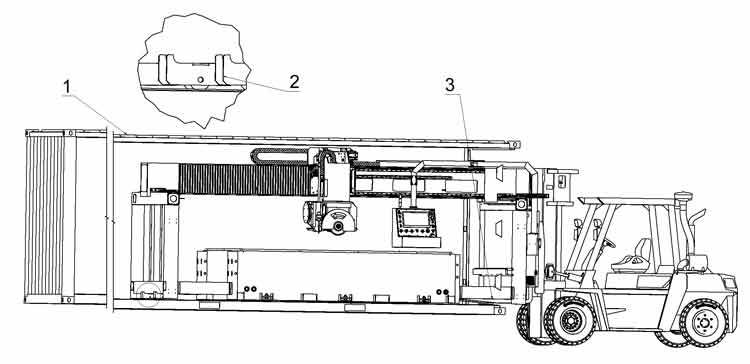
- Place container on the floor.
- Insert wheels on both sides in the back.
- Use wheels in the back and forklift in the front.
pull out machine enough so it can be lifted with a crane.
Use the appropriate hooks and holes to lift the machine with appropriate crane, be sure that your lifting belt or chain can hold the weight and see if the machine rests straight while lifting.
¶ Machine Installation Leveling
Read the placing chapter of this manual for correct placement information.
Remove the Y axis locking brackets, and locking screws on both sides you used to lift the machine.
Remove the X and Y axis RED shipping fixtures
Remove the brackets that hold the control panel on the bridge.
Install the safety bolts to prevent the arm of the control to enter the working area.
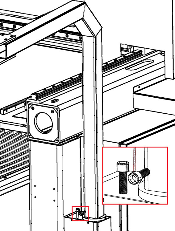
Fit the back frame on both sides of the machine, and make sure line up the linear rails and the racks.
On the right side pass all the cables trough, and plug them up.
While lining up the rails make sure the taper alignment pin fit properly, hammer them in after lining up and before completely tightening the bolts
Tighten bolts to securely assemble the back side of the Y rails.
Pay particular attention to the joint of the Y rails on each side while tightening the Y rails, there must be a smooth transition between the two parts of the rail
Install the door, frame in front of the machine, and the camera arm.
Make sure to plug the camera USB cable into the small SBC in the box behind the camera arm.
Check the highest rail side of the machine, keep that point as reference and use water level tube to level the machine, start by level Y rail with highest point, use hydraulic jack to help you lift machine if needed, Adjust the level of the machine by adjusting the screws inside the machine feet.
Level the opposite side, but keeping the reference level from the side already levelled
Tighten the center feet front and back of the table, and check all levels again, keeping the same reference side.
Double check the level, make sure all machine feet touch the floor, also check again the Y rail joint smooth alignment.
Assemble the other covers and bellows, connect all waterjet joints, use blue goop on waterjet threads.
Connect electrical power, details in electricity chapter
Connect water, details in water chapter
Then power on the machine, details in put to use chapter.
If you encounter problems please check attached troubleshooting.
Machine is now leveled and safe to operate to work with, please refer to the CNC and CAM software manuals to learn how to program the machine.
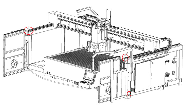
¶ Electricity
Find and plug all the green plugs for power, make sure the cables on the bottom and top plugs are numbered the same.
The main power supply needs to be hooked up to L1 L2 L3 and ground, and only for 380V machines also the Neutral, please look at machine name plate for Voltage and Wattage to calculate proper cable size.
Connect the 3 phases L1 L2 L3, and the ground (PE green/yellow), and Neutral blue N only for 380V machines.
If for any reason you need to replace the cable of the machine, make sure the supply cable it’s the same size or bigger than the one supplied.
Check power input to be from 220V or 380V ±10% depending on name plate of machine.
Always check the machine label to calculate proper amperage of machine to mount proper safety devices according to regional regulations, please trust label printed Voltage and Kw over this manual.
Before connecting the supply cable check that the main switch in electrical box is OFF and main supply is OFF.
The power source must have a residual current device according to local security law (normally 0,03 Ampere)
It is recommended to connect the machine to a separated ground, such as a 20mm ground rod into the ground.
ATTENTION: If oil pump does not function properly even though it has been filled with oil, it is necessary to invert two of three cables of phases.
ATTENTION: Only the electricians can open the box and execute maneuvers or repairs
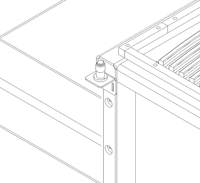
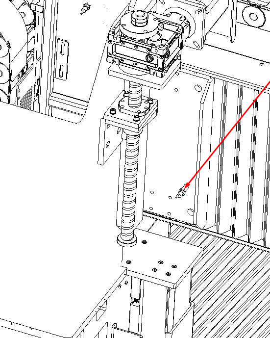
¶ Mount the probe
Mount the probe on the back right side of the table, the screws are already in the holes to fix the probe, but the probe is unmounted and will be found in separate wrapping, keep the probe top level slightly lower than the table rubber table, plug the cable wire should be zip tied nearby.
¶ Hydraulic Pump and Oil
The Hydraulic pump is situated on the right side of the machine in auxiliary box.
Open the door of auxiliary box, which is next to electrical box, you will see it.
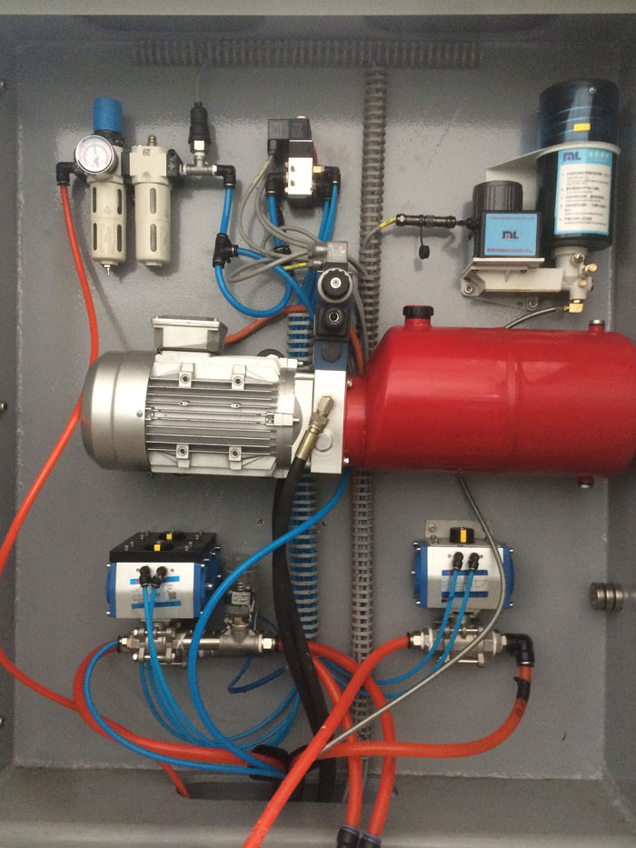
Find the hydraulic pipes from inside the machine frame, and pull them to the pump, there are only two hydraulic pipes, there is visible black tape to show the proper order of the pipes.
Remove the top plugs, and fill the pump with oil Hydraulic oil 46 (not supplied with machine), the plug has a level gauge, use it to fill the pump properly; do not fill the pump completely full.
¶ Placing + environmental conditions
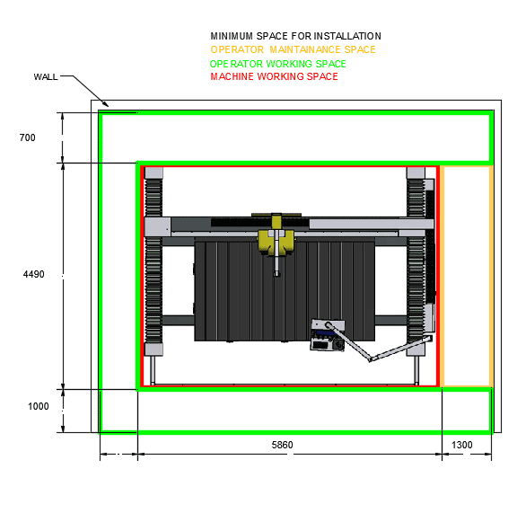
The machine does not demand particular environmental conditions. It must be installed indoor – in production hall. The hall has to be illuminated, ventilated and provided with flat concrete pavement. To place the “ORBIT A5 SawJet” study the designs 2.3.A. and 2.3.B., make sure that the electrical box door can be opened to do maintenance.
Control if the “ORBIT A5 SawJet” is not moving while working..
The minimum temperature of the hall does not have to be less than 4/5 °C (40 F); the maximum temperature does not have to exceed 40 °C (104 F).
NOTE: Never expose the machine to direct solar beams. If the temperatures exceed the standards contact the technical service.
¶ Lighting system
The lighting system in production hall must respect the norms EN 12464 the lighting of workplaces or ISO 8955 the customer needs to make the light night system for the machine at norms. It has to provide good visibility in every part of the machine. It must eliminate reflections, which would be dangerous during operating. The lighting system has to ensure good visibility of the display and the emergency button.
On special demand the working zone can be equipped with one ulterior source of light.
¶ Vibrations
In consistent and correct way using of the machine, vibrations are not in such levels to create dangerous situations.
¶ Sonorous emissions
The machine is designed to avoid or reduce the level of sonorous emission maximally. The level of emitted acoustic emission in the workplace does not exceed 85 dB. The measured value for the machine is 83.9 dB and declaration constant K = 4 dB.
NOTE: values of indicated noisiness are levels of emission and they do not represent real operating levels necessarily.
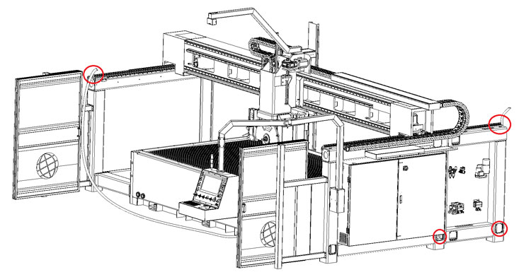
¶ Water Connection
The machine main water supply is located in the auxiliary box of the machine.
Make sure your connections are in conformity with the local laws of security.
The valve on the right it's for the sprinkles to wash the parts on the table, the water can be clean tap water or recycled 5~10 microns
The left front valve it's for trough spindle water, here clean tap water is recommended.
The left back valve it's for blade water, recycle water is recommended here as long as the water doesn't contain big particles like wood splinters and such.
Connect the water directly to the water valves in auxiliary box of the “ORBIT A5 SawJet”.
The thread on all valves is a half inch NPT female thread.
Water pressure: minimum 2 bar, maximum 4 bars.
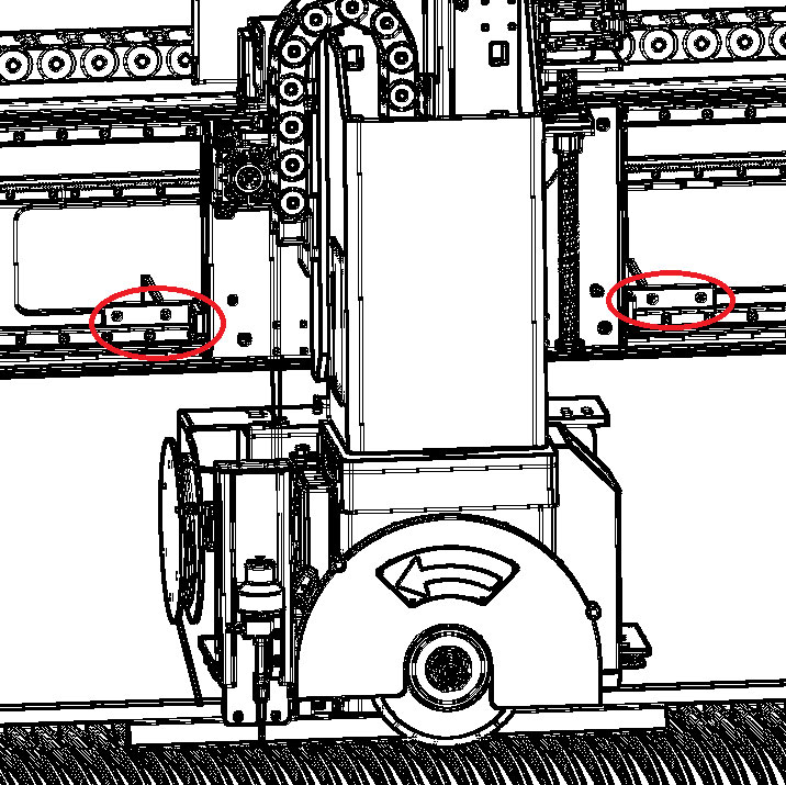
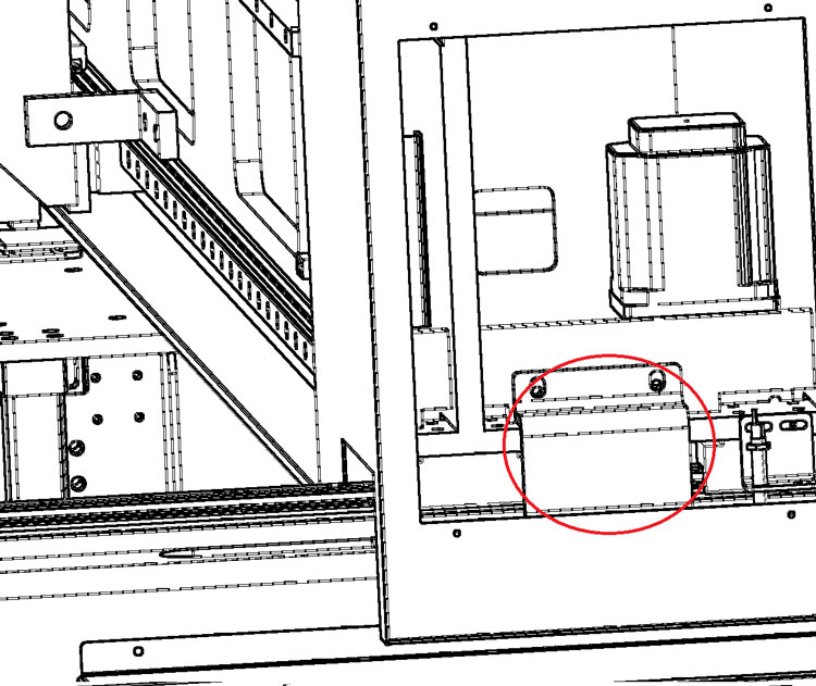
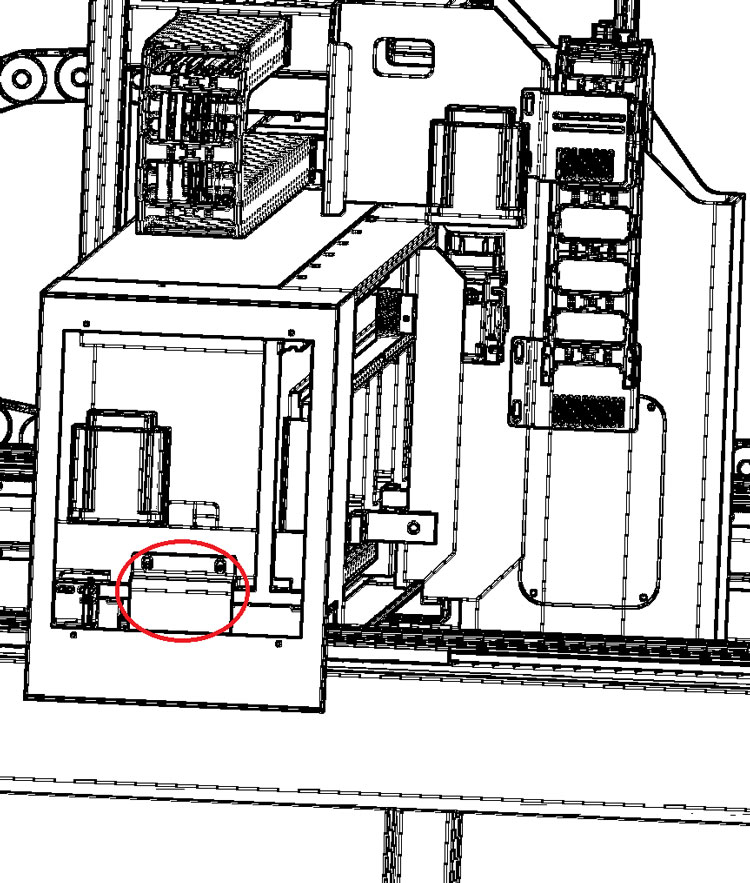
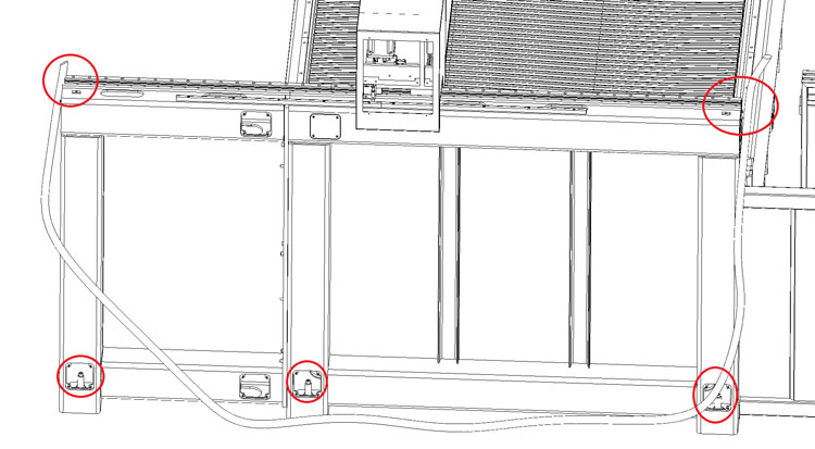
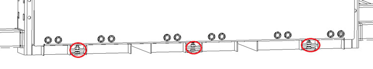
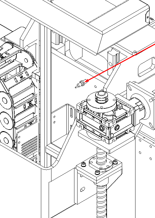
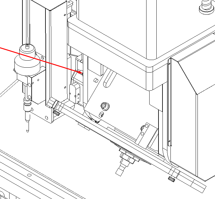
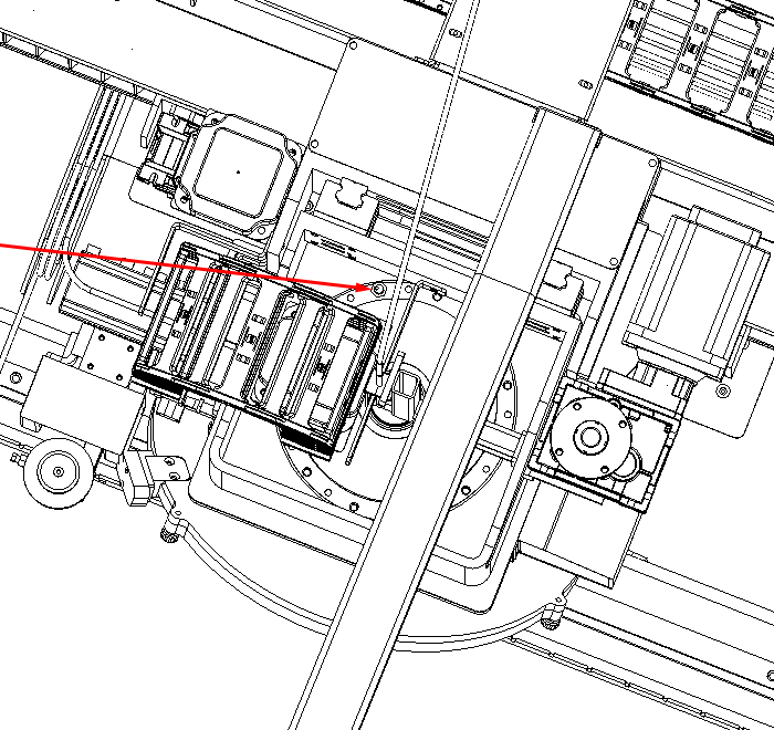
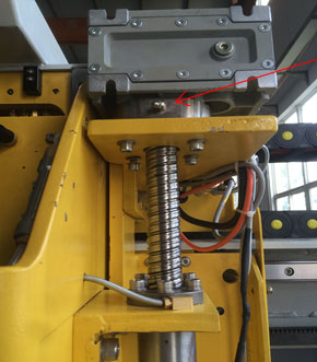
¶ Sensor placement
This is an explanation of where all the homing sensors on the machine are located
Joint0 X Sensor (remove cover on the head to access)
Joint1 Y1 Sensor (on the left side of the machine)
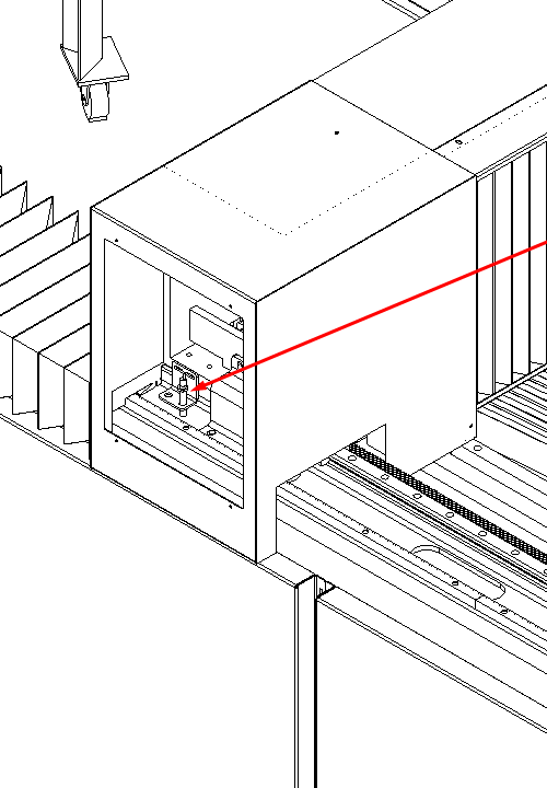
Joint7 Y2 Sensor (on the right side of the machine)
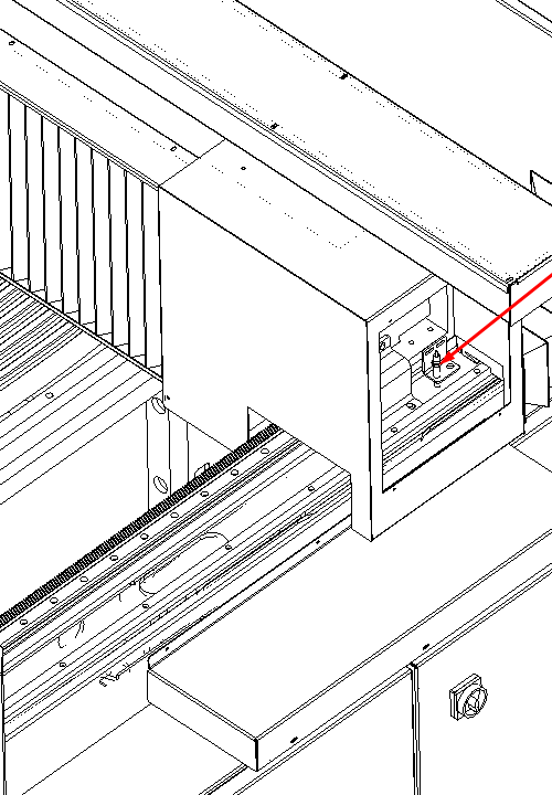
Joint2 Z Sensor (remove cover on the head to access)
Joint3 B Sensor (behind the blade)
Joint4 C Sensor (remove cover on the head to access)
¶ Put to use
¶ Preliminary controls
Installation and the first start of the machine have to be tracked or executed from AitalMAC technician. In the best way the technician of AitalMAC should collaborate with the technician of the customer who will have therefore possibility to acquire a maximum of information for working with the machine and maintenance subsequently. Before putting in the function it is necessary to make following checks to avoid errors or incidents during the starting of the machine:
- Check if the machine is not damaged after shipment or placement,
- Check (with a multi-tester) interconnection between the electrical box, control panel and other connections,
- Check connections of all external sources (water, electricity), check for leaks,
- Check the free movement and eventual free spin of all mobile parts of the machine.
- Make sure all axis can move and move in the right direction like indication on machine, contact factory if machine moves wrong.
- Check the correct function of all the sensors, all sensor are proximity sensors, use a metallic object and place it in front of the sensor to trip it, see in the machine CNC manual interface when the sensor trip in the I/O page it will be displayed clearly. Contact factory if sensors are not tripping.
Turn the main-switch turn the “enable key” (5) on and push the “power” button (2). If the power button does not light, please check fuses inside electric panel.
Also, power on the PC, and double click on the Orbit A5 SawJet shortcut on the desktop to open the machine control program.
Press the switch on button on the interface

if you are not able to move the machine and you are welcome by a “Joint0 on limit switch” error message, is because one of the limit sensors is on the limit, Joint0 will be X, Joint1 Y and Joint2 Z, Joint 3 is B, Joint 4 is C, and Joint 7 is Y2, to move the machine out of the limit, simply click the override limits check in JOINT part of manual page, then press switch on button on software interface
you will now be able to move the machine out of the limit, by clicking on the Joint tab and choose the axis in limit from the drop down list and moving over with the MOVE+ or the MOVE- buttons.
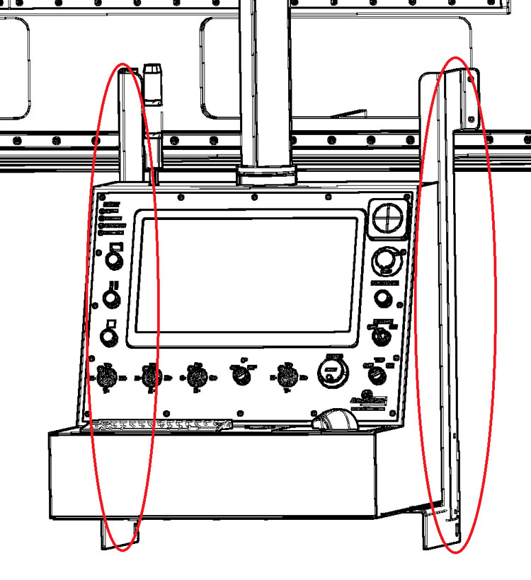
¶ Description of the control board
 |
(1) Screen/Monitor/Display of the machine |
 |
(2) POWER BUTTON has two functions, first function is to power on the machine when enable key is on, the second function is the power on button of the CNC controller, CNC controller power button functions the same as a computer power button, if you press twice too quickly then it won't power on, if you hold for 6 seconds CNC controller will shut down, this functions persists whether the key is on or off or the POW. ON button light is on or off. |
 |
(3) EMERGENCY STOP for stop the machine in emergency cases (on the control panel) |
 |
(4) General switch I\O selector for turn on and off the machine from the electric panel, it's recommended to turn off the PC and controller before turning the General switch off, you can only open the electrical cabinet door if the switch is on the off position |
 |
(5) Enable Key, to enable and disable machine motion, turning this key to the left (off) will turn off the machine and the power on button, and you will not be able to switch on the power until the key is to the right (on) |
 |
(6) TCP toggle, to enable and disable machine tool center point motion, with this toggle to the left (off) the machine motion will be relative to each singular axis not effected by the rotational axis, with the toggle to the right (on) the machine motion will be relative to the tool cutting direction, this kind of motion is effected by the rotational axis |
 |
(7) AUTOMATIC BUTTON for starting the automatic functions |
 |
(8) PAUSE BUTTON for enter suspend state. |
 |
(9) STOP BUTTON for stop automatic functions |
 |
(10) Speed control wheel for the movement of all axis |
 |
(11) Angle toggle of B and C rotational axis, there are three angles of choice: 0° the rotation is free 45° rotation is in 45° increments 90° rotation is in 90° increments |
 |
(12) I/O button for panel computer |
¶ Starting the machine
Make sure the General switch is on (4), release the emergency stop (3), turn the enable key to the right on (5), press POW. ON button once (2), press the I/O to power on the panel computer (12), wait for red light to go on (about 2 minutes), then open the Machine Application.
If the machine fails to boot visit boot fail and connect for more details
Click the switch on button on interface
wait till the interface is completely enabled to start working
¶ Working with the machine
The operator of the machine must have pre knowledge of a CAD program, the operator must read carefully and understand the CAM and CNC programs manuals, and watch carefully the video tutorials.
The machine was designed and constructed to cut kitchen tops and vanity tops, to do this it’s necessary to design the shape of the sink in a CAD program and save it as a DXF file (a CAD program is provided in the machine PC), then import the DXF in the CAM program, and setup the blade cuts to cut out your designed parts, then post-process the cuts g-code.
After starting the machine, use parking button to park the machine, and use the table up and down buttons in manual page under table tab to lift table and load the stone, then lower the table, from the automatic page in the machine program load and start the start the g-code to let the machine cut the stone automatically.
The stone can alternatively be cut with manual operations from the machine application, or with simple X and Y cutting pages also in the machine application to cut simple strips.
¶ Stopping the machine
¶ Stopping the machine during automatic process
Press the Esc button on your keyboard to stop the machine (this will only work if the machine program is active).
Press the stop button on interface.
Press red stop button on the panel (9).
In case of emergency push the emergency button (3)
¶ Stopping the machine when finish working
To stop the machine, use the enable key (5) then close taps (water and air supply). Then shut down the PC. If there is a risk that ambient temperature will go under 5°C (40 F) it is recommended to leave the machine on to avoid damage of electronic cards.
¶ Manually change tool on machine
To manually change blade tool please unfasten the knobs holding the cover for the blade, and take off the cover.

Then use the two provided spanners to unfasten the nut (counterclockwise)

Once the nut is unfastened, pull out the flange and the blade, and load the new blade, the blade mounting shaft diameter is 50mm, once the new blade is loaded, put back the flange, fasten back the nut, and mount the cover and lock it with its knobs.
¶ Interpretation of terms
¶ Main switch
The main switch on the electrical box has to be switched on to start the ORBIT A5 SawJet. You must power off the switch in order to open the door of the electrical box.
¶ Control panel

The control panel with his monitor is the operator interface with the machine, provided with Pegasus and ORBIT A5 SawJet programs.
On the panel there is also an emergency button, to press in case of emergencies, the machine enable key, and the power on button of the machine, on top of the emergency there is the power on button for the panel computer, and on top of the screen you can find the status lights. On left of the screen there are three colors of buttons. The green button is automatic button. The yellow button makes the machine enter suspend state. The red button is used to stop. There are also controls at the bottom of the screen. The angle toggle of B axis knob is in the center. Speed control button is on the left of TCP toggle.
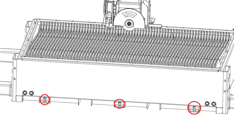
¶ Head

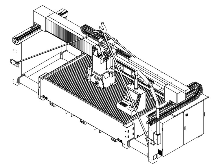
The head of the machine is the central part of the machine, the up and down movement of the head is the Z axis, the back-and-forth movement is called Y axis, and the spinning of the head around Z is called C axis, the inclination of the blade up to 90 degrees is called B axis.
On the machine head is mounted the spindle or main/blade motor, on which the diamond blade is mounted to cut stone.
¶ Table

The table is in welded steel, but it will be covered in either wood cement or rubbers or plastic materials according to customer discretion, the table can be lifted up to allow easy loading of the stone slab.
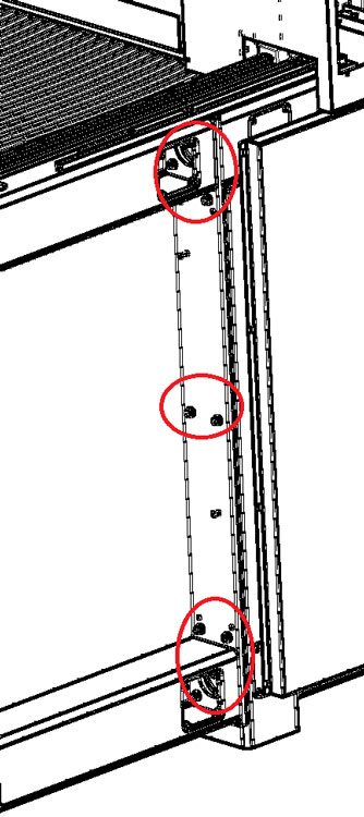
¶ Electrical box

The electrical box is mounted in the right side of the machine, inside you can find all electrical components of the machine, inside you will find also the 9 axis CNC controller, you should keep the door locked, and open only after properly powering off the machine from the main switch.
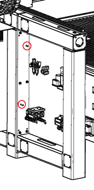
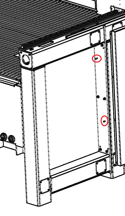
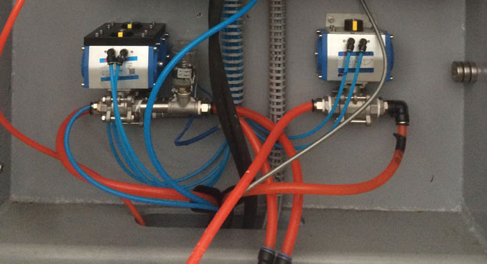
¶ Auxiliary box

The auxiliary box is next to the electrical box. The auxiliary box has hydraulic pump, water connection, air pressure meter, the lubrication system and so on. Some auxiliary equipment of the machine is inside.
¶ Bridge or X bridge

The bridge of the machine is supported by the shoulders, the head of the machine slides to the left and right on the bridge, this movement is called X axis which is controlled by joint 0 motor.
¶ Y rails, or Y ways

The Y rails are located up the two sides of the machine, and on the shoulders of the machine slide forward to backward, creating the Y axis movement.
¶ Feet

The feet of the machine are the parts that sit on the floor. The machine has six feet. There is a screw inside each foot that can adjust the height of the foot. When the machine is on the ground, the feet height need to be adjusted to make the machine levelled and stable.
¶ 9 Axis CNC controller
The 9 Axis CNC controller is located inside the electrical box, it controls the whole machine, the control panel interface connects to the CNC controller to get control of the machine.

¶ Lubrication
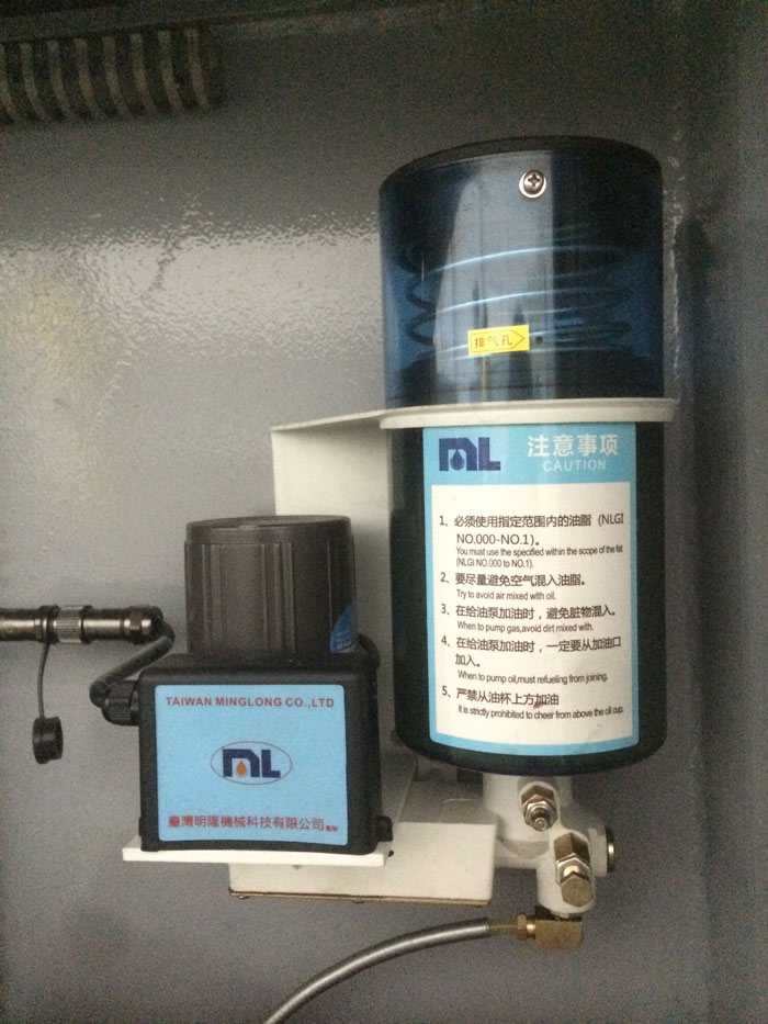
Use a grease pump to fill the grease system with #00 or #000 grease and machine will pump grease regularly when spindle is on. The machine program has settings for the grease pump frequency. Caution Labels are attached to the grease lubrication system. Please read it carefully.
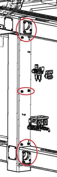
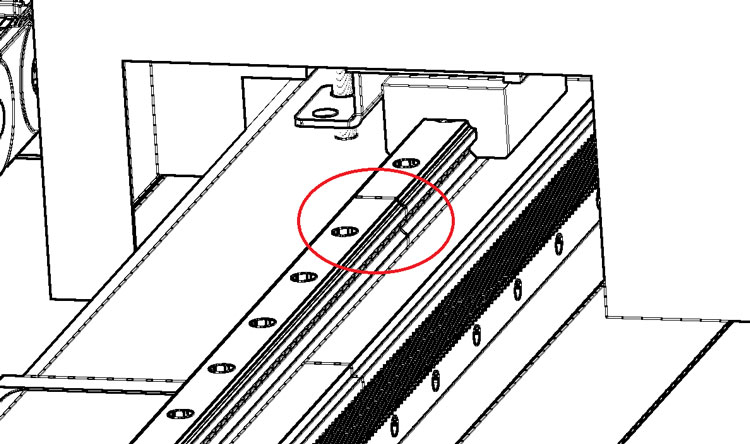
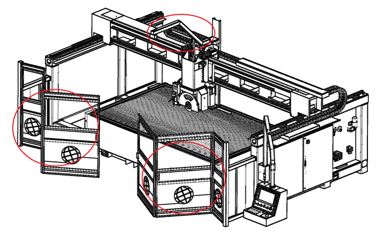
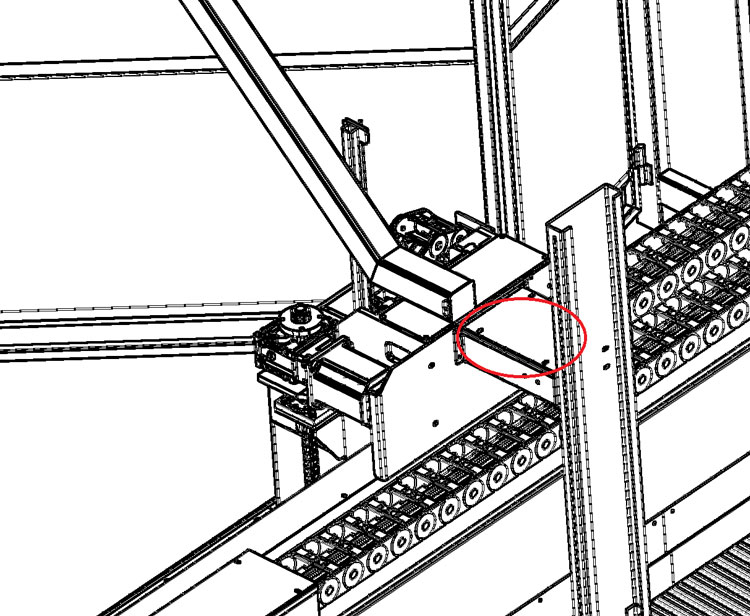
The automatic grease pump takes care of most lubrication but not all, operator still needs to manually pump grease in the Z bearings once a year, also the table hinges, and the racks of X and Y axis.
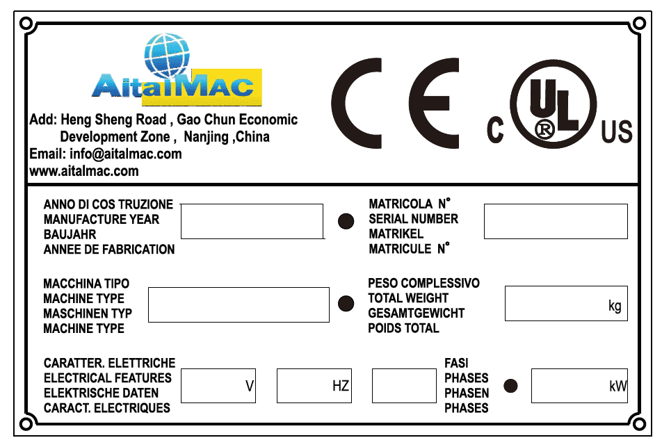
¶ Label
The label with data regarding the machine is situated on the right side of the ORBIT A5 SawJet, on the top of the electrical box. There are marked data which producer will ask for in case of complaint.
¶ Operation
The ORBIT A5 SawJet can be operated from the CNC only in Manual or Simple linear cut mode, or it needs to be programmed i to process fully automatic job. The CAD (DraftSight or any CAD) is used to draw the shapes the machine has to work. The CAM (AitekCAM or any other CAM with appropriate post processor) is used to program the cuts on the CAD shapes, and saves them as g-code. The CNC program is used to play this g-code on the machine, the CNC program can also move the machine in manual, or start simple linear cuts.
Parts on the ORBIT A5 SawJet sit on the machine table; the parts are located on the table either by measuring off the table and use the table in the CAM as reference, or by acquiring the location with the laser pointer on the machine. Optionally the machine can be mounted with a camera that will photograph the parts and display their location in the CAM interface.