Aitalmac Co.,LTD
Add: Hengsheng road 001#,Gao Chun
economic development zone.
Nanjing, 211300 P.R. China
Tel: 0086-25-57311800
Fax: 0086-25-57889845
Web: http://www.aitalmac.com
¶ Water Treatment WTPV3 Manual
Copyright © 2022 by AitalMAC Co., LTD
¶ Introduction
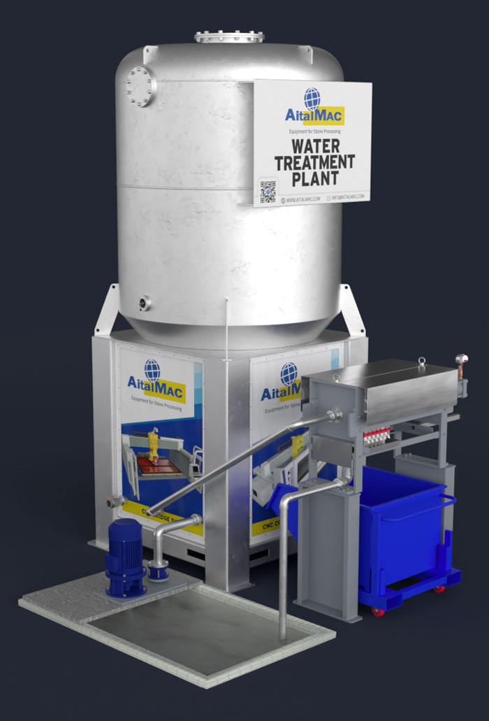
Congratulations, you have just bought your Water Recycling System WTPV3. The WTPV3 is the AitalMAC's solution to treat and supply recycled water to your machines.
The WTPV3 has a touchscreen panel with easy to use software. The WTPV3 was designed to work by itself and need only weekly inspection and maintenance in normal conditions.
To facilitate it's use, we, the constructor, have included a manual of our product. We advise you to read this manual carefully, it contains useful information about installation, use and maintenance of your Water Recycling System. It will result in longer life and easier use.
¶ General information
¶ Constructor
The company AitalMAC has been constituted by Mr. Romeo Toniolo, which has extensive experience in designing and constructing machines for natural and artificial stone processing. After years of research and development, and repeatedly proving itself reliable with suppliers and trading companies all around the world, AitalMAC has acquired extensive technological know-how and a upstanding reputation which represents the best warranty for AitalMAC’s customers.
¶ General description
WTPV3 is a Water Recycling System.
Description: The Aitalmac filtration system for the stone industry utilizes a filter press and a pit for containment and can be described as follows:
Filter Press: The filter press is a device used to separate solids from liquids through a filtration process. It consists of a series of filter plates that are pressed together to create a filtration chamber. The solid material is retained by the filter plates, while the filtered liquid passes through them.
Containment Pit: The containment pit is used to collect and contain the liquid from the stone processing. This pit is designed to prevent leakage or spillage of the liquid, ensuring that it is collected and managed properly.
The filtration system works as follows: The wastewater from the stone processing is collected in a pit of suitable size for the system. The liquid is suctioned from the pit and pumped into the settling tank, where it is centrifuged with chemicals for faster settling (Coagulant and flocculant). The settled liquid in the settling tank is then pumped to the filter press for compaction of the sludge into more or less dehydrated panels, while the surface liquid returns to the stone processing.
- Filtration: By applying pressure, the filter press compresses the filter plates, allowing the liquid to pass through the plate pores and collecting it in containment pockets, while the solids remain inside the filter press.
- Solid Collection and Disposal: The solids collected within the filter press need to be managed and disposed of properly, according to current environmental regulations.
- Management of Filtered Liquid: The filtered liquid is collected in the pit for stone processing wastewater.
- Management of Clarified Water: The clarified water remains in the pressurized tank, ready for use.
This filtration system, using a filter press and containment pit, enables the separation of solids from liquids in the stone industry, contributing to efficient and responsible treatment of the materials and liquids involved in the process.
¶ System characteristics:
On the model WTPV3 the main tank structure is made of welded steel hot galvanized, on the Filter Press structure a final coating of epoxide painting enamel.
The Main Sludge Pump feeds sludge water to be filtered and pressurized for other machines or tools to use.
The electric cables used on the WTPV3 are resistant to dust and wear and tear. All sensors used on the WTPV3 are watertight.
The power electric box is positioned under the main tank, the box is equipped with AitalMAC's Control System, the system is equipped with a touchscreen monitor with user friendly AitalMAC's software interface.
The Filter Press when full will be opened and cleaned by the system, and then closed back.
¶ Warranty
The warranty of the system is 1 (one) year from the date of the effective installation by AitalMAC’s or third-party engineers. In case of eventual faults or defects on material or manufacture the customer has to inform the producer or the relevant sale agent about the problem by registered letter immediately. If the complaint is accepted from the producer – he will replace and/or repair the components (the system or its parts). In the warranty are not included expenses for disassembling, assembling, sending of parts, and expenses regarding the producer’s engineer (food, accommodation, trip). The reparation of the respective component does not mean reopen of the warranty period for the whole system (only in case of replacing of the system). The producer is not responsible for damages brought about from customer or third party due to wrong handling with the system. From the warranty are excluded parts which were accidentally damaged during the transport, during the lifting and placing of the system, due to wrong connection to the electrical feeding line (these are included if those operations are provided by the producer). From the warranty are excluded components mechanically or atmospherically worn due to insufficient maintenance or unforeseen or forbidden use. The producer is not responsible for not authorized modifications or repairs. The validity of the warranty is subordinated to the corrected execution of the maintenance like described in this manual. For components supplied from third party valid warranties of third party.
This warranty covers only parts of the System with brand Aitalmac sold by Aitalmac and its subsidiaries, affiliates, authorized resellers, or country distributors.
The term "System" is limited to the hardware components, does NOT include applications or programs, third party products or devices without the Aitalmac brand.
The warranty period starts from the date of purchase, as indicated from the tax document or other such document.
In order to receive assistance in warranty, it may be required to provide proof of purchase.
To the extent permitted by local law, new systems and any product or replaced component, may contain new materials or used with equivalent performance and reliability. Any replaced product or part will have same functionality or at least equal to the original product or component replaced. Replacement parts are warranted to be free from defects in materials and workmanship for a period of 6 months if greater than the remainder of the period of warranty of the system in which they are installed.
If during the warranty period Aitalmac is notified of defects in the system covered by this warranty, Aitalmac will repair or replace the product, but if Aitalmac requires the defective component to be returned, Aitalmac will have no obligation to repair, replace or refund until the defective part is returned.
In the case of recurring failures of components, Aitalmac at its sole discretion can decide whether to replace the product with one same or equivalent in performance, or refund the purchased price.
¶ Exclusions
This limited warranty does not apply to consumables or to products which have been removed of serial number or have been damaged or rendered defective due to accidents, misuse, intentional misuse, contamination, virus infection, improper maintenance or calibration or inadequate or other external causes;
Also, to software, interface, parts or supplies not provided by Aitalmac, improper preparation or maintenance on the site where the system is installed, loss or damage in transit, or to modifications or assistance by unauthorized parties.
For systems, the use of tools of third parties does not affect this warranty or any assistance contract with Aitalmac. However, if the fault or defect were attributable to the use of third-party tools, Aitalmac will charge the standard time costs and that of the materials for the intervention.
As a precaution against corruption or loss of data, back up periodically the data stored on hard drivers or other storage devices, AitalMAC is not responsible for damage to or loss of any programs, data, or the restoration of any programs or data other than the factory software from Aitalmac.
¶ Limitations of Warranty / Local Laws
Aitalmac makes no other warranty or condition of any kind, whether express or implied warranties or conditions of merchantability, satisfactory quality, and fitness for a particular purpose. Aitalmac expressly disclaims warranties and conditions not expressly stated in this warranty statement. Any implied warranties imposed by law are limited to the duration of the applicable warranty period.
Some states do not allow time limitation on implied warranties, or the exclusion or limitation of incidental or consequential damages for products intended for the consumer, nor the rights of the consumer. In such states or countries some of the exclusions or limitations in this warranty may not apply to the purchaser.
This warranty is applicable and may be enforced in all countries in which Aitalmac or an authorized service center Aitalmac offer service in warranty, it being understood, however, that the availability of the service and the time of intervention may vary from country to country and may be subject to legislation in the country of purchase. For details contact the service center Aitalmac or an authorized representative.
This limited warranty gives the purchaser specific legal rights, which may vary from state to state and country to country. For exact rights the buyer is obliged to acquaint themselves with the legislation in force in the state or in the country of affiliation.
the warranty terms contained in this statement, except to the extent allowed by law, do not exclude, restrict, or modify but are in addition to the mandatory rights applicable to the sale of this product to the purchaser/final client.
¶ Limitation of Liability
To the extent permitted by law, the remedies provided in this warranty are the sole and exclusive remedies available to the buyer.
These terms and conditions supersede and cancel any prior contract or statements, including those found on sales documentation by Aitalmac or opinions provided on behalf of Aitalmac to the purchaser in relation to the purchase.
To the extent permitted by law, except for the obligations specifically set forth herein, in no event Aitalmac be liable for any damages caused by the product or the failure of the same, including any direct, indirect, special, incidental or consequential damages, whether based on contract, tort, and other legal interpretation and regardless of AitalMAC that has been advised of the possibility of such damages. Aitalmac shall not be liable for any claim of reimbursement made by third parties or made by the purchaser on behalf of third parties.
¶ Software Technical Support
Technical support for the software Aitalmac and third-party software preinstalled by Aitalmac is available at Aitalmac using different contact methods, including electronic media and telephone, for five years from the date of purchase.
How to contact Aitalmac:
In case of need for warranty service or technical support during the warranty period, contact your local assistance AitalMAC. The addresses found at: http://www.aitalmac.com.
When you call AitalMAC or an authorized service center AitalMAC you must have available model name and serial number of the product, any error messages and the type of operating system.
After reading the user manual and maintenance!
¶ Settlement of customer’s expenses
On the base of documentation by constructor (if there is no another agreement between customer and constructor) customer has to provide on his expenses following:
- Preparation of the hall – basement, drainage (see Placing),
- Water supply in conformity of norms in the country of use, (see Water Connection),
- Supply of electricity in conformity of norms in the country of use, (see Electricity)
- Hydraulic oil #46 for hydraulic pump control cylinder filter press.
- Compressed air 7 bar
- Coagulant and flocculant ( see Coagulant and flocculant)
¶ Assistance center
AitalMAC's Water Systems can get service ONLINE.
AitalMAC has its primary assistance center in its residence, and other centers distributed around the world. For every help or information contact sale agents of AitalMAC in your country to ensure the assistance center which is close to you, or contact directly the head office of AitalMAC Company. Agents will help you detect and solve all problems; retailer or constructor will require dates of product marked on the label on the system.
If the system needs the intervention of a technician, Aitalmac can provide the technical staff that might be prepared personal of the dealer or distributor or authorized third parties.
The system has no parts that are not replaceable by the customer himself, all parts are easy to replace.
Aitalmac does not consider correct for anyone in the distribution network, to add costs to the system sales value, for assistance services.
Aitalmac considers proper to assist with technical staff if required, but for a fee, during or out of warranty.
¶ About manual
The Customer must read with extreme attention all information written in this manual. Exhaustive study of manual, preparation, installation and right use of the system constitute the base of the good relationship between constructor and producer.
¶ Purpose of the manual
The purpose of the manual is to give the customer all necessary information so that he would be able to install and work with the system by his own in the most independent and sure way. It comprises inherent technical information, information about function of the system, security and maintenance.
NOTE: Before starting of whichever operation on the system the customer must read carefully contained instructions in this manual. In case of any doubts on the corrected interpretation the constructor must contact producer or sale agent for necessary clarifications.
¶ Addressees of the manual
The manual is appointed to the operator of the system and to the customer’s technician as well. The customer must explain carefully function of the product to both of them.
NOTE: The constructor is not responsible for any of damages eventuate from insufficient perusing of this manual.
¶ Conservation of the manual
The manual is not printed but is online. It is recommended to make another copy of this manual (with attachments) and keep it in a safe place in office.
NOTE: The system does not have to be yielded to third party without informing the constructor. (The constructor must verify that the system respects all norms in the country of use at the moment of the cession in case of incident. All parties, which have contracted the system, are incumbent in pecuniary penalty).
¶ Installation
¶ Transport and store
While transporting the system beware:
- The system is locked and cannot move.
- The system is sitting on the side transportation brackets,
- The Filter Press is blocked (you can use strings),
- The system is drained of all water,
- The system is nailed with steel to the floor so it cannot move.
While lifting the system beware:
- Your lifting equipment is supporting 3000 kg,
- You are using only the lifting points,
- When the strings are tight you will not damage any part of the system.
- Use forklift truck, from the side only when extracting system from the container.
- When using a forklift truck, see if the system rests straight while lifting.
While storing the system beware:
- The system is stored on a dry and clean place.
- Do not store the system outside.
¶ Lifting and handling
Place container on the floor, remove the turnbuckles fixing the system to the container, and extract the system from the container using a forklift (3Ton at least) till the system is out enough to be lifted with a crane
- Place container on the floor.
- Pull out system enough so it can be lifted with a crane.
Use the appropriate hooks and holes to lift the system with appropriate crane, be sure that your lifting belt or chain can hold the weight and see if the system rests straight while lifting.
¶ System Installation Leveling
Read the placing chapter of this manual for correct placement information.
Connect electrical power, details in electricity chapter
Connect water, details in water chapter
Then power on the system, details in put to use chapter.
If you encounter problems please check troubleshooting.
System is now leveled and safe to operate to work with.
¶ Electricity
Find and plug all the green plugs for power, make sure the cables on the bottom and top plugs are numbered the same.
The main power supply needs to be hooked up to L1 L2 L3 and ground, and only for 380V systems also the Neutral, please look at system name plate for Voltage and Wattage to calculate proper cable size.
Connect the 3 phases L1 L2 L3, and the ground (PE green/yellow), and Neutral blue N only for 380V systems.
If for any reason you need to replace the cable of the system, make sure the supply cable it’s the same size or bigger than the one supplied.
Check power input to be from 220V or 380V ±10% depending on name plate of system.
Always check the system label to calculate proper amperage of system to mount proper safety devices according to regional regulations, please trust label printed Voltage and Kw over this manual.
Before connecting the supply cable check that the main switch in electrical box is OFF and main supply is OFF.
The power source must have a residual current device according to local security law (normally 0,03 Ampere)
It is recommended to connect the system to a separated ground, such as a 20mm ground rod into the ground.
ATTENTION: If oil pump does not function properly even though it has been filled with oil, it is necessary to invert two of three cables of phases.
ATTENTION: Only the electricians can open the box and execute maneuvers or repairs
¶ Hydraulic Pump and Oil
The Hydraulic pump is situated under the main tank.
Find the hydraulic pipes from the Filter Press, and pull them to the pump, there are only two hydraulic pipes, there is visible black tape to show the proper order of the pipes.
Remove the top plugs, and fill the pump with oil Hydraulic oil 46 (not supplied with system), the plug has a level gauge, use it to fill the pump properly; do not fill the pump completely full.
¶ Filter Press
The filter press should be placed next to the system, and connected to the bottom of the tank
After installation, the filtropress needs to be adjusted for the water output from the panels. The valves on the plates are adjusted by closing them to regulate that the last panel releases more water than the first, while maintaining a flow that allows the machine to function properly. Inside the right side of the tank, there is a level sensor. This sensor must detect the presence of water in the tank during the filtration process. If no water is detected, it assumes the mud is dry and initiates the mud expulsion cycle. The water coming out of the filtropress should be returned to the collection pit using a 2-inch pipe. A smaller pipe would impede the proper functioning of the filtropress.
¶ Flocculant tank
The flocculant tank must be filled with water and flocculant at appropriate rate according to your use.
¶ Coagulant and flocculant
Coagulant and Flocculant
The use of coagulant and flocculant depends on the specific process and the nature of the water to be treated. Generally, the coagulant is used to aggregate suspended particles in the water, while the flocculant is used to form larger flocs that can be easily settled. To determine the correct dosage of coagulant and flocculant, it is necessary to conduct tests or follow the instructions provided by the chemical product manufacturer. Typically, you start with low dosages and gradually increase them until the desired level of coagulation and flocculation is achieved.
To perform the test, take a water sample from the process using a 10-liter container for ease of calculation. Mix the water sample as you would mix a minestrone soup. Gradually add the coagulant using a graduated syringe, drop by drop, until you observe the formation of flocs in the water. Then, add the flocculant, also drop by drop, until you observe the settling of the flocs.
It is important to note that this test was conducted on a 10-liter sample, and to adapt it to a volume of 400 liters, the quantities of coagulant and flocculant need to be increased by a factor of 10. The results obtained during the test will help determine the optimal dosage for water treatment in the process.
However, it is important to consider that the test was performed in a few minutes, while it takes at least 40 minutes for the incoming dirty water to reach the outlet channel of the tank. Therefore, it is recommended to start with a dosage of 1/4 of the test result. Adding too much chemical can result in the deposition of sediment in the machine drain channels, while using insufficient amounts may leave the water still turbid, although it won't cause any issues to the machinery or processes. Remember, less chemical is better than too much. The heavier particles, which are the ones that could cause problems, will still settle in the tank even without the use of chemical agents.
If you encounter difficulties during the process, do not hesitate to ask for our assistance. We will be happy to help.
To correctly relate to the display and achieve the correct dosage of coagulant or flocculant, it is important to consider that the quantity bar always refers to 400 liters. For example, if you want to use 5 cc of coagulant or flocculant for 400 liters, simply set the display to 5 cc. However, using only 5 cc for 400 liters may not allow for a uniform mixing of the chemical agent with the incoming dirty water. Therefore, to achieve proper dilution and a dosage of 20 cc per 400 liters per minute, it is necessary to increase the dilution of the coagulant or flocculant by at least 5 times.
¶ Placing + environmental conditions
The system does not demand particular environmental conditions. It must be installed indoor – in production hall. The hall has to be illuminated, ventilated and provided with flat concrete pavement. To place the “WTPV3” study the designs ahead, make sure that the electrical box door can be opened to do maintenance.
Control if the “WTPV3” is not moving while working..
The minimum temperature of the hall does not have to be less than 4/5 °C (40 F); the maximum temperature does not have to exceed 40 °C (104 F).
NOTE: Never expose the systems electrical components to direct solar beams. If the temperatures exceed the standards contact the technical service.
¶ Lighting system
The lighting system in production hall must respect the norms EN 12464 the lighting of workplaces or ISO 8955 the customer needs to make the light night system at norms. It has to provide good visibility in every part of the system. It must eliminate reflections, which would be dangerous during operating. The lighting system has to ensure good visibility of the touch panel.
On special demand the working zone can be equipped with one ulterior source of light.
¶ Vibrations
In consistent and correct way using of the system, vibrations are not in such levels to create dangerous situations.
¶ Sonorous emissions
The system is designed to avoid or reduce the level of sonorous emission maximally. The level of emitted acoustic emission in the workplace does not exceed 85 dB.
¶ Pit
Sizing of the collection pit:
1.1. The collection pit should be positioned as close as possible to the machines that use water to avoid liquid dispersion through evaporation and sediment accumulation in the collection channels.
1.2. The correct containment pit should have a capacity of approximately 20-25 cubic meters of liquid. The normal service level will be around 10 cubic meters, while an additional 10 cubic meters are needed to recover water in case of system failure. The ideal dimensions of the pit are 4 meters by 3 meters with a depth of 3 meters.
1.3. A grid must be installed at the entrance of the pit to prevent the entry of dirt such as bags, cardboard, cigarette butts, wood, etc. Only liquid should enter the collection pit.
Note: If the collection pit is located 100 meters away from the working area, it is important to consider that it will take a few minutes for the water to return from the processing. If 400 liters per minute of water are being used and it takes 5 minutes for the water to return, the capacity of the pit will need to be increased by 2000 liters. However, it is still recommended not to have a pit with a capacity less than 10 cubic meters, as some water is lost during the processing. Even during polishing, where theoretically clean water should be used, it may not be sufficient, and there is a risk of running out of water in the pit. If it is not possible to build an adequate pit, it is necessary to install a float valve to replenish the water lost during processing with water from the public water supply. The float should be positioned at a level that introduces water only when the system is low on water. Turn on the machine, open the water to the machines, and observe the water level in the pit as it decreases. The float should be positioned a few centimeters below the service level.
¶ Water Connection
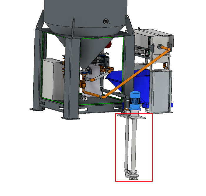
The system incorporated a sludge pump, the bottom portion in the red rectangle in the picture below must be placed in a pit with sludge water, before the first start the system's tank needs to be filled with clean water.
In the sludge pit avoid large floating particles like splinters, or anything larger than 10mm to be sucked in, the pit must be full and big enough to maintain a constant flow of water, it must not be possible to extinguish water below the bottom level of the sludge pump during normal operations, the sludge pump output pipe must be connected to the inlet of the tank, must be 2-½ inches diameter to allow good flow.
The outlet must be connected to the recycled water which will feed your tools and machines with recycled water pumped by the system. the outlet is a 2 inches female thread.
Make sure your connections are in conformity with the local laws of security.
Water pressure: 2 to 3.5 kg/cm˄2 for normal operation, maximum 6 kg/cm˄2 for cleanse processes.
¶ Sensor placement
The pressure sensor is placed above the output valve
The output flow sensor is just below the pressure sensor.
¶ Put to use
¶ Preliminary controls
Installation and the first start of the system have to be tracked or executed from AitalMAC technician. In the best way the technician of AitalMAC should collaborate with the technician of the customer who will have therefore possibility to acquire a maximum of information for working with the system and maintenance subsequently. Before putting in the function it is necessary to make following checks to avoid errors or incidents during the starting of the system:
- Check if the system is not damaged after shipment or placement,
- Check (with a multi-tester) interconnection between the electrical box, panel and other connections,
- Check connections of all external sources (water, electricity), check for leaks,
- Make sure hydraulic pump spins in the clockwise direction, reverse the input phases to reverse direction if necessary.
- Check the correct function of all the sensors. Contact factory if sensors are not functioning.
Turn the main-switch on. The system will boot, and start pumping, if not please check all breakers.
¶ Description of the control board
 |
(1) General switch I\O selector for turn on and off the system from the electric panel, you can only open the electrical cabinet door if the switch is on the off position | ||
| PICTURE OF TOUCH PANEL | (2) Touch panel | ||
¶ Starting the system
Make sure the General switch is on (1)
Wait till the touch panel is completely loaded and the system will start automatically.
¶ Working with the system
On boot the system will always close the filter press and try to reach desired pressure on your recycle water, the inlet will be open, the outlet will be opened, and the pump will be running at maximum speed, till pressure in the tank is stable at the requested pressure on the touch panel, set the pressure to 0, or tap Manual MODE to interrupt this behavior.
Once the desired pressure is reached the system will keep pumping at variable speed as long as there is water flowing out, when there is no water flowing out and desired water pressure is reached and stable for 20 seconds the inlet valve closes and the sludge pump stops.
As water flows out, the system will pump flocculant at the inlet, user can change the rate of flocculant being pumped at the touch panel.
When the system is at desired pressure, it will run the filter press routine, with intervals from 5 to 120 min, which can be adjusted on the touch panel.
The filter press routine will run even when there is no water flowing out, as long as desired pressure in the tank can be maintained.
See User interface chapter for more in depth information
¶ Stopping the system
¶ Stopping the system during automatic process
Tap Manual MODE on the touch screen to stop the system automatic cycle.
In case of emergency turn off the General switch (1)
¶ Stopping the system when finish working
To stop the system, Tap Manual MODE check on the touch screen. If there is a risk that ambient temperature will go under 5°C (40 F) it is recommended to leave the system on to avoid damage of electronic cards.
¶ Interpretation of terms
¶ Main switch
The main switch on the electrical box has to be switched on to start the system. You must power off the switch in order to open the door of the electrical box.
¶ Touch Panel
PICTURE OF TOUCH PANEL
¶ Electrical box / Electrical Panel
PICTURE OF Electrical box / Electrical Panel
¶ Flocculant tank
PICTURE OF Flocculant tank
¶ Sludge Pump
PICTURE OF Sludge Pump
¶ Filter Press
PICTURE OF Filter Press
¶ Lubrication
The lubrication tank at the air inlet should be filled with air tool oil, to maintain the the pneumatics in good conditions.
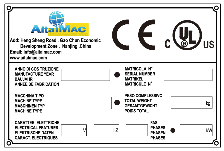
¶ Label
The label with data regarding the machine is situated on the side of the WTPV3. There are marked data which producer will ask for in case of complaint.
¶ User Interface
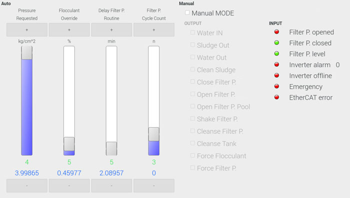
This is the main user interface that allows you to control the automatic process, and manually operate the system. In the next chapters each portion of the user interface will be described in detail
¶ Pressure Requested
This vertical bar displays the water pressure desired by the user, it can be adjusted with a tap on + or on - button from 0 to 4 kg/cm˄2.
The green value it's the desired pressure that's been set, the blue value it's the pressure feedback, from the pressure sensor at the outlet of the system.
The system will dynamically regulate the sludge pump speed, to maintain requested pressure set by the user.
At pressure 0 the pump stops and the inlet valve stops.
¶ Flocculant Override
This vertical bar displays the override on the rate of flocculant to water out, it can be adjusted with a tap on + or on - button from 0 to 100 %.
The green value at the bottom is the current flocculant override value in liters per minute, the blue value it's the current flow of water out as read by the out flow sensor.
The system will regulate the flocculant pump rate of pumping, the rate is linked with the sensor of water flowing out times the user specified override, the more water is flowing out the faster the flocculant pump will run, but the override balances the pumping rate according to user preference, a higher override will pump more even if there is less water flowing out, but in both cases if there is no water flowing out or if the flocculant override is set to zero the flocculant pump will stop, a 5% override is recommended.
¶ Delay Filter P. Routine
The vertical bar displays the time that the system will wait before running the next filter press routine, it can be adjusted with a tap on + or on - button from 5 to 120 minutes.
The green value at the bottom is the currently set delay time, the blue value at the bottom is the current elapsed time waiting to run filter press cycle.
The system will run filter press routine when the elapsed time reaches the delay time set. The filter press routine will open the bottom valve of the tank and the sludge water present at the bottom of the tank will be pumped to the filter press, the filter press will fill up with the muddy particles in the sludge, at the same time the filter press will feed clean water back to the pit, when the filter press is full of compacted mud bricks it will not be able to feed anymore clean water, the system has a small sensor that will read the filter press flow level to be low (also displayed on touch panel as "Filter P. level"), this is used to count Cycles, see next chapter for details
¶ Filter P. Cycle Count
The vertical bar displays how many filter press compacting routine cycles to run successfully run with the filter press full (unable to feed clean water from the taps), before running the filter press shake clean cycle, it can be adjusted with a tap on + or on - button from 0 to 10 cycles.
The green value at the bottom is the desired filter press compacting cycles to run, before running the filter press shake clean cycle, the blue value at the bottom is the counter of how many filter press compacting cycles have successfully run at this time.
The system will count one cycle only if the system is in pressure and the Filter Press level sensor senses no water coming out the Filter Press, the user can set how many cycles to count before running filter press cleaning, each cycle is 5 minutes long, it is recommended to run about 3 cycles to compact the mud at 3~4 kg/cm˄2 of water pressure.
The counter will reset when the counter matches the desired count, if the desired count is set to 0 the filter press cleaning cycle will run the next time the Filter Press is found to be full, regardless of current count.
¶ Manual MODE
The Manual MODE stops all automatic cycles, closes all valves and the pump, user can then use each of the Manual check marks to run simple actions on the system to check for proper functionality, or other user cases, following a description of each check mark in detail.
¶ Water IN
When this check is on the inlet valve opens, and the pump will start, and will try and reach pressure set on pressure requested.
¶ Sludge Out
Direct control of the bottom central valve, to send sludge to the filter press.
¶ Water Out
Direct control of the outlet valve, this valve sends recycled water out to other machines.
¶ Clean Sludge
Direct control of the clean sludge valve, this valve is between the inlet and bottom of the tank, it is used to redirect the pumped sludge from the pit, to attempt unclogging filter press and/or the tank, see more details in the cleanse chapters.
¶ Open Filter P.
Direct control of filter press opening function, when checked starts the hydraulic pump and turns on the solenoid to open up the filter press, they both will go off when the “Filter P. opened” sensor goes on.
¶ Close Filter P.
Direct control of filter press closing function, when checked starts the hydraulic pump and turns on the solenoid to close the filter press, they both will go off when the “Filter P. closed” sensor goes on.
¶ Open Filter P. Pool
Direct control of the Filter Press Pool, will retract the pool away from under the filters when on, should always be turned on before Opening the filter manually, to avoid mud to fall in the pool.
¶ Shake Filter P.
Direct control of the Filter Press shaking, when on the shaking cylinders will perform the shaking action, going up and down.
¶ Cleanse Filter P.
Run a 5 second cleanse of the Filter Press, to be run when the filter press is empty but it's not feeding out any clean water when running the filter press cycles.
The water in valve will be force closed, the Clean Sludge valve will be opened, the central valve to direct sludge to the filter press will be opened, the pump will then go at max speed for 5 seconds, the check mark will turn off automatically after 5 seconds.
This is to attempt to unclog the filter press with high pressure, if successful the filter press will start to feed clean water from the valves, the water is redirected from the sludge pump directly to the filter press, the sludge pump it's forced at high speed to increase the pressure to attempt to push out the solid mud that may have the system stuck at the entry point in the filter press.
¶ Cleanse Tank
Run a 5 second cleanse of the bottom of the tank, to be run when the filter press is empty but it's not feeding out any clean water when running the filter press cycles.
The water in valve will be force closed, the Clean Sludge valve will be opened, the central valve to direct sludge to the filter press will be force closed, the pump will then go at max speed for 5 seconds, the check mark will turn off automatically after 5 seconds.
This is to attempt to unclog the bottom of the tank, serves similar purpose to cleanse filter press, but in this case it's presumed that the clog is at the bottom of the tank, therefore a high pressure jet of sludge from the sludge pump, will be sent directly at the bottom of the tank pushing back up, to attempt to disrupt the solid mud clog at the bottom of the tank.
¶ Force Flocculant
To run flocculant pump even tough there is no water sensed at the outlet, this maybe enabled and will also force the flocculant in automatic mode, this is in case the water out sensor does not sense flow of water out anymore, or if user desires to check flocculant pump, or pump flocculant in to compensate for low levels of flocculant in the recycling system, the amount can still be adjusted from the flocculant override bar
¶ Force Filter P.
To force a filter press cleaning cycle, the filter press will be opened, shook clean and closed back, during this cycle the whole manual user interface is locked to prevent errors.
¶ Filter P. Opened
Input signal of the sensor to let system know the filter press is fully opened, green when filter press is open, the sensor is located behind the first plate of the filter press.
¶ Filter P. Closed
Input of the pressure that stops the filter press cylinder when closing, the filter press it's closed in pressure by the max level of the pressure gauge on the filter press cylinder, green when filter press is above closing pressure.
¶ Filter P. level
The input to sense if the filter press is feeding clean water out, the sensor is located at the water recollection pool at the far side of the filter press, for proper function, the recollection pool it's drained quickly by the larger hole at the top, which feeds clean water back into the pit quickly, and it's drained slowly by a smaller hole at the bottom, make sure that the smaller hole it's not clogged, the level sensor will be on (green) when the level is low, and red when the level is high, when the level is low it means that there is little to no clean water flowing out the filter press, indicating that the filter press full cycle should be counted.
¶ Inverter Alarm
Indicates that the inverter of the sludge pump had an error, and the error number is indicated next, refer to the Inverter powtran pi9000 manual page 163 for details.
All automatic operations will be stopped when the alarm is on.
¶ Inverter Offline
Indicated the inverter of the sludge motor is currently offline, this maybe due to a bad communication cable, or the inverter is off due to the breaker been tripped, which may signal an overload or a short.
All automatic operations will be stopped when the alarm is on.
¶ EtherCAT Error
Indicates that the control system has lot connection with the main control boards, contact support for more details.
¶ Manual emergency
If the operator notices any anomaly in function of the system during the working he has to immediately stop the system. In case of emergency turn the main switch off. After finding and solving the cause of the problem the operator can restart the system again
¶ Restoration
To restart the system, turn the main switch on.
¶ Reparations precautions
Attention: In case of detection of any anomaly or problems first of all check that the operator follows all instructions in this manual. In case of real problems all reparations has to be executed immediately after finding the problem or anomaly to avoid increasing of problems or breaking of other components. In case of any reparation is necessary to switch off the main switch.
¶ Safety
¶ Presuppose use
The system is designed and constructed to recycle sludge water containing mud particles.
Thanks to the touch panel user interface with which the system is supplied, operator can adjust the recycle to desired performance.
¶ Forbidden use
The system does not have to be used:
- For uses different from those present in chapter Presuppose use
- In explosive, aggressive atmosphere or where is high concentration of powders or oil substances in the air
- In place with risk of fire
- In place with inclement conditions
- In place with electromagnetic radiation
- In place which not allow safe operating of the system
- For recycling of not suitable particles.
¶ Dangerous zones
The only dangerous zone it's the filter press while it's closing, do not attempt to clean the filters while the filter press it's closing, always keep your hands out of reach of the filter press plates while the system is operating.
¶ Arrest functions
Functions of arrest of the system are following:
- The main switch - general interrupting
¶ Security work
The WTPV3 is developed to eliminating all risks correlated to its use. But it is no possible to eliminate risks of eventual accidental contacts between the system and hands of operator. Correlated residual risks would be cause of unskilled or uninstructed operator, they are following:
- Position - due to not correct position of the operator during operating the system.
- Tangling up - due to incorrect working dress (or not opportunely adapted).
- Training - due to lack of the training regarding operating of the system.
NOTE: To reduce all consequences of the aforesaid dangers is always necessary to follow all instructions in the manual in scrupulous way.
¶ Residual risks
During the normal cycle of working and the maintenance the operator is exposed to some residual risk, which, for the nature of operations, cannot be totally eliminated.
¶ Before you start
- a new operator must always read the manual and get safety instructions from an habituate user,
- check always the electric connections on eventual damages
- do always the daily checks before starting the system
- Is the system clean?
- Nobody during repair or maintenance took off a piece of the system?
¶ Working
- It is safe to let the system run unattended
- have daily inspections of flocculant and filter press status
- look out for alarm signals on the touch panel
¶ After working
- clean always the system and its environment properly
- set system in Manual MODE, or turn off the main switch if you do not desire the system to recycle your water
¶ The workshop
- the system has to stand immovable
- avoid cables and hoses being in the way
¶ Equipment
- wear always safety shoes when near the system
- wear always safety gloves while loading doing maintenance
- wear always ear protectors while near the system
¶ operator
The system is constructed so that one operator can work with it.
- The operator has to be informed about all information necessary for operating the system and trained for it.
- The operator has to study the manual carefully and understand it clearly.
- The operator has to be able to understand and interpret designs and outlines in manual correctly.
- The operator has to know all hygiene and technical norms and norms for safely working on the system.
- The operator has to know the work environment of the system.
- The operator has to know what to do in case of emergency (where provide aids, how to use them).
- The operator must have adequate technical preparation.
¶ Technical data
¶ Electrical design
¶ Spare Parts
¶ Maintenance
Note: never use graphite grease to lubricate any part of the machine.
¶ Cleaning
For clean the machine is necessary to obey all following points:
- use always protecting glasses, mask, and boots during purification of the machine,
- in case of using special cleaners or products (petroleum) use always protecting gloves,
- never use thinners or solvents on rubber parts of the machine,
- in case of using water for washing do not use hot water and keep out of electrical parts
ATTENTION: Before washing always unlink the machine from electrical source. Never wash the control board or interior of the electrical box with water.
¶ Daily purification
After working wash the filter press with water, make sure the recollection pool is clean and the little hole on the drain pipe is not clogged.
- clear carefully the floor under and around the system
- empty the compressed mud tank
- refill flocculant as necessary
¶ Check EVERY DAY
- Water leaks
- Proper electrical connection
- Proper air connection
- flocculant level
- filter press not clogged
- drain pipe little hole not clogged
- recollection pool is clean
- filter press closed properly
- check the electrical box on waterproof
- check place where the display is mounted on waterproof
- check all the functions of the system
- water level at the pit is proper
- all valves are functioning properly
- cables, pneumatic pipes, and hydraulic pipes have no visible damage or leaks
- sludge pump motor is dry
¶ Dismissal
By renewal of the oil the dirty oil has to be collected carefully (also in case of leaks) and send to a specialized company to recycle.
By total dismissal of the machine, it can be send back to the constructor who will take care of the dismantling and recycling.