¶ Make picture from Orbit application
First take picture from the Orbit Application
Make sure you have a connected device to get the picture, you can look on the bottom left of the program, if there is a device available but you get a black picture, from the take picture page, click on REOPEN CAMS that should solve the problem, If camera is still not found checkout cannot find cam
To properly adjust the picture, for the cameras that take 4 shots, you need to cut 9 squares of 2cm or 3cm stone (use stone thickness you will use more often) 250mmx250mm or 10"x10", for single shot camera only 4 pieces will be enough.
LOOK CAREFULLY AT THE STONES IN THE MIDDLE OF THE TABLE, PAY ATTENTION AT HOW THEY ARE NOT CENTERED IN THE TABLE, BUT THEIR SIDES ARE!!
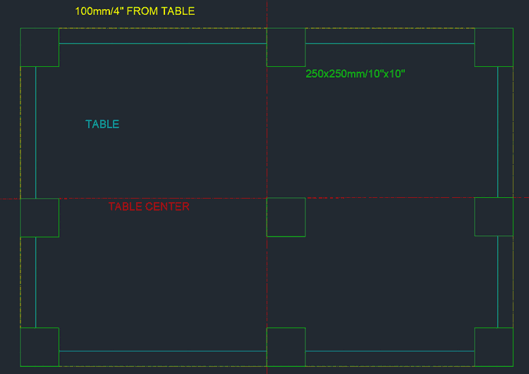
Now you should get the X and Y coordinates of the table, the table should be square with the machine, you need to use the back of the blade and line it up with the yellow line in the drawing above, basically 100mm from the table edge, once you are lined up read the position of machine, you will need to spin the head around to get to all 4 sides of the table, you should get the left and right sides X position, and the bottom and top sides Y position, once you have these values we are ready to setup the table in orbit program.
X left = -20
X right = 3280
Y bottom = 250
Y top = 2250
Let's take these value as our four positions of the table sides with the 100mm/4" contour, now go in the parameter page in the Orbit application, for this hypothetical table the values to set are as in this picture
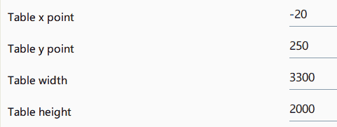
"Table X point" is the left side, "Table Y point" is the bottom side, then you need to calculate table width (X right - X left = 3280 - (-20) = 3280 +20 = 3300), and the table height (Y top - Y bottom = 2250-250 = 2000)
After adjusting table size make a picture of the table, click on each image, you will see an overlay of which you can move the corners, for 4 pictures move the corners of the overlay so that one picture is one quarter of the table use the sides and corners of the squares laid on the table for reference, for one picture you only need the tables plus 100mm/4" all around (50mm/2" will also be OK, if you the picture cannot fit 100mm/4")
The picture is ready to be imported in Pegasus, the table size in Pegasus can only be changed by users with a dealer key, contact your dealer to do this final step.
Open Pegasus and choose workbench "Pegasus Workbench Definition" open the recent files and you should have the machine table, if not you should find it in "C:\Pegasus Data 3\Marble\Objects\WorkBench", delete the old table (purple rectangle) and create a rectangle for the new table, you can draw with the X and Y coordinated of the sides taken from before, and then offset on the inside 100mm/4" to get the actual table size, delete the bigger rectangle, and in definition tab, click on add display geometries, then click on the table rectangle and right click to make it a display geometry, save the table and you can close the workbench application, now use Dimensions from 2D CAD to get the picture rectangle size or use the ones from Orbit, they should be the same.
Open Pegasus Cutting, make a new file if you had it already opened, like this the new table will be loaded from the workbench file, make a rectangle from 2D CAD the same size as the rectangle of the workbench, then make an offset on the outside for the 100mm/4", now make a line from X0 Y0 to the bottom left corner of the table, then either mirror the line in X and then in Y from X0 Y0, or rotate the line 180 degree around X0 Y0. Import the image and make sure rectify image is off (if you recently updated Pegasus go in file menu "P" on top left, configuration photo and choose camera), then click on create configuration file, and add a new configuration, first page on the right just confirm, real width and real height are the sizes of the rectangle we drew, thickness use the thickness of the stones you used to cut the picture in Orbit application, then click OK and then click on the end point of the line that we made before (the end not on X0 Y0), then write a name for this configuration, at this point the configuration is created and can be selected when importing the picture, you will have to reactivate rectify picture, and if that's the only configuration if will directly size the picture to the size of the rectangle, matching size and position of the table, to make other thickness, offset the rectangle on the inside if thickness to do is thicker and on the outside if it's thinner, offset of half the difference in thickness, then make another line and turn 180, and follow the instructions again to make another configuration with another name.
Instructions are also available in video format here