¶ 1 AitalMAC Ui
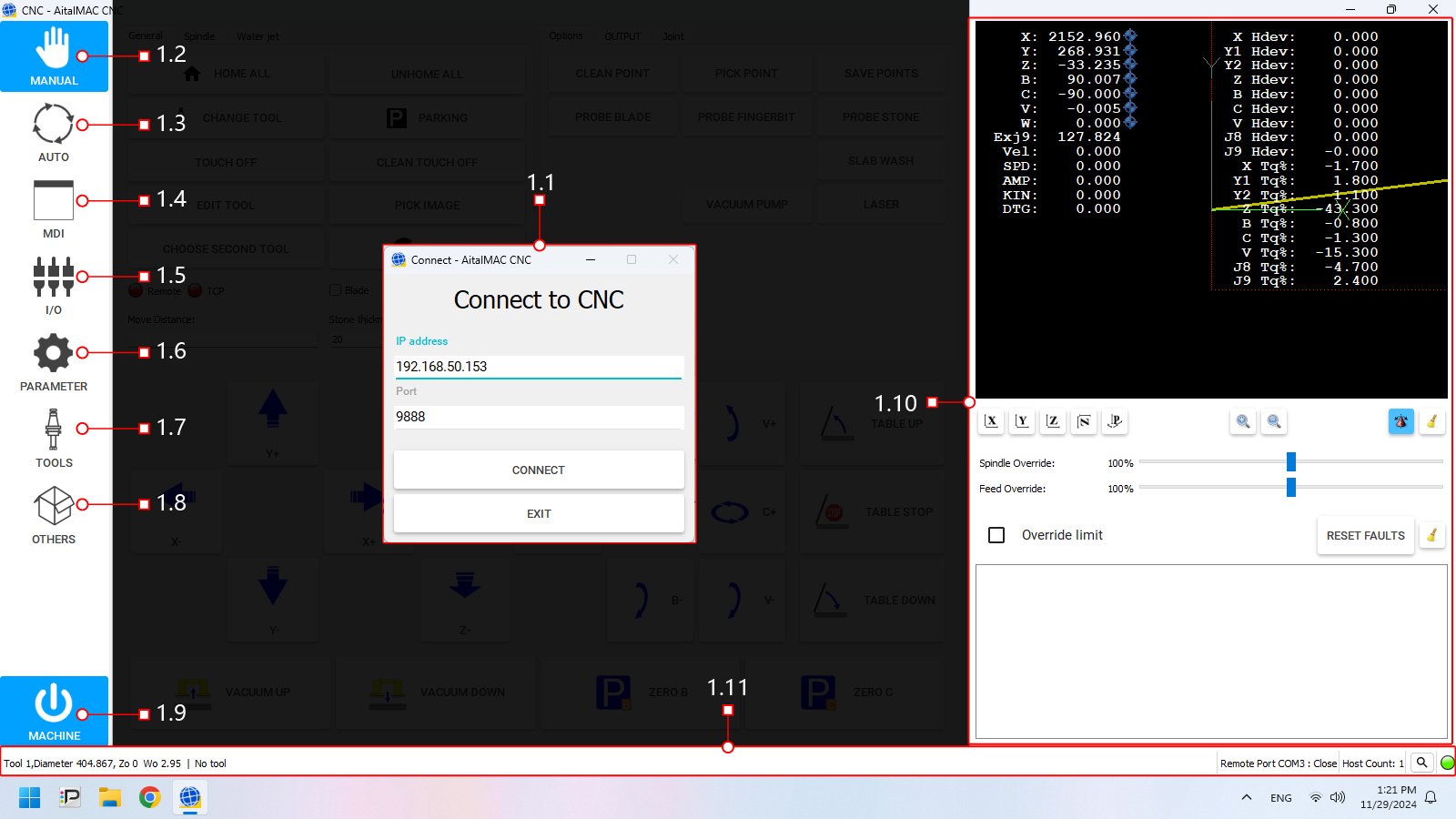
Figure 1: The AitalMAC application User Interface as it's displayed before connecting
The software interface is divided into distinct sections, each serving a specific purpose. Below is a breakdown of the main components:
-
- Connection Status: Enables users to connect to the CNC controller.
- Behavior: When the software connects to the CNC controller automatically at startup, this page is skipped, and users are taken directly to the manual interface.
-
Activity Bar (Left Side)
A vertical panel located on the left side of the interface. It is used to switch between different pages or activities within the software, each corresponding to a specific function or operation of the CNC machine.
- Manual: Access the manual control page for direct machine manipulation and jogging.
- Auto: Switch to automatic operation, where preprogrammed toolpaths are executed.
- MDI (Manual Data Input): Input and execute G-code commands manually.
- I/O: Monitor digital Input/Output signals of the machine and view machine working hours.
- Parameters: Navigate to the parameters page for configuring machine settings and system variables.
- Tools: Access Tool Manager, where you can create tools, set feeds and speeds for manual operations, and configure tool offsets.
- Others: Various additional tools are available, most notably the Remote Control settings.
- Machine: This button enables/disables machine operations. Colors indicate enabled state. Machine faults prevent activation and display errors.
-
- 3D Preview: Displays a visual representation of the machine or toolpath, aiding in real-time monitoring.
- Machine Position and Torque Information: Numerical or graphical data about the machine's current position and applied torque.
- Message log area: Displays system messages, errors, and warnings for easy troubleshooting and status updates.
-
A toolbar on the bottom section of the interface displaying key information about the current machine:
- Loaded Tool: Indicates the currently loaded tool in the CNC machine.
- Other Info: Including machine status, active program, and system warnings.
¶ 1.1 Connect Window
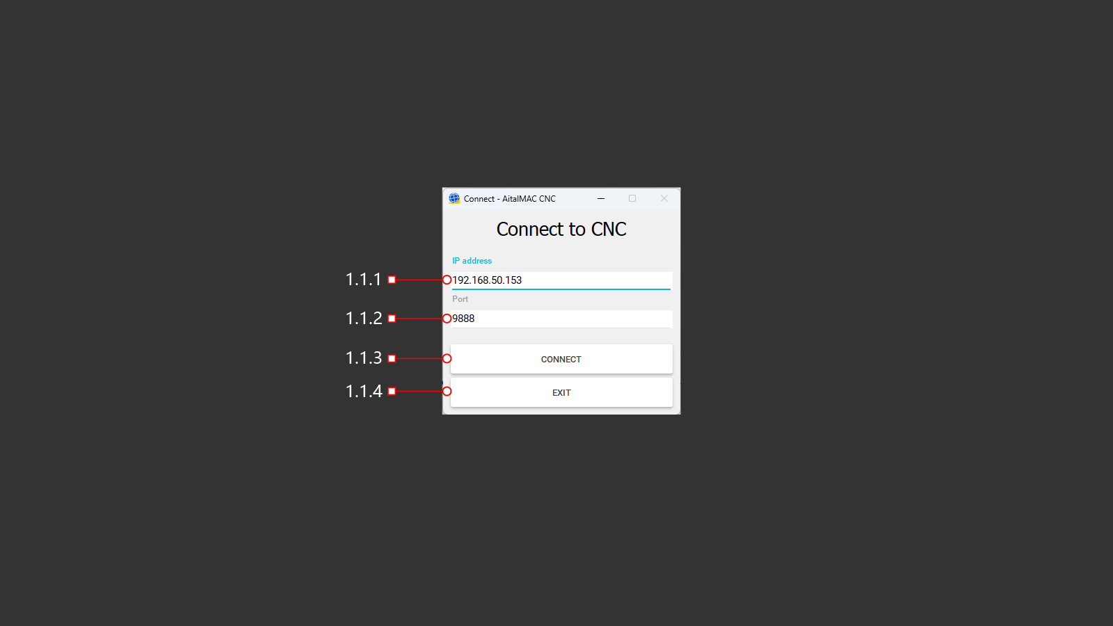
Figure 1.1: The Connect window which only appears when automatic connection fails
The Connection Window appears when the software starts up and cannot automatically connect to the CNC controller. It allows users to establish communication between the software and the CNC controller.
- Purpose: Ensures that the software can connect to the CNC controller hardware before proceeding to other activities.
- Behavior:
- If a connection is successfully established at startup, this page is bypassed, and the user is taken directly to the manual interface.
- If the connection fails, this page remains active, providing the user with options to retry the connection or exit the program.
¶ 1.1.1 IP Address
The text input field to enter the network IP address of the CNC machine for establishing a connection.
- Default Value: The default IP address for a single AitalMAC machine is 192.168.50.152 (for machines within a line, this increments for each machine—153, 154, and so on)
¶ 1.1.2 Port
The numerical input field to specify the port number required for the connection.
- Default Value: The default port for AitalMAC machines is 9888.
¶ 1.1.3 Connect
The button to initiate the connection process using the details entered in the IP Address and Port fields.
¶ 1.1.4 Exit
The button to close the program.
¶ 1.2 Manual
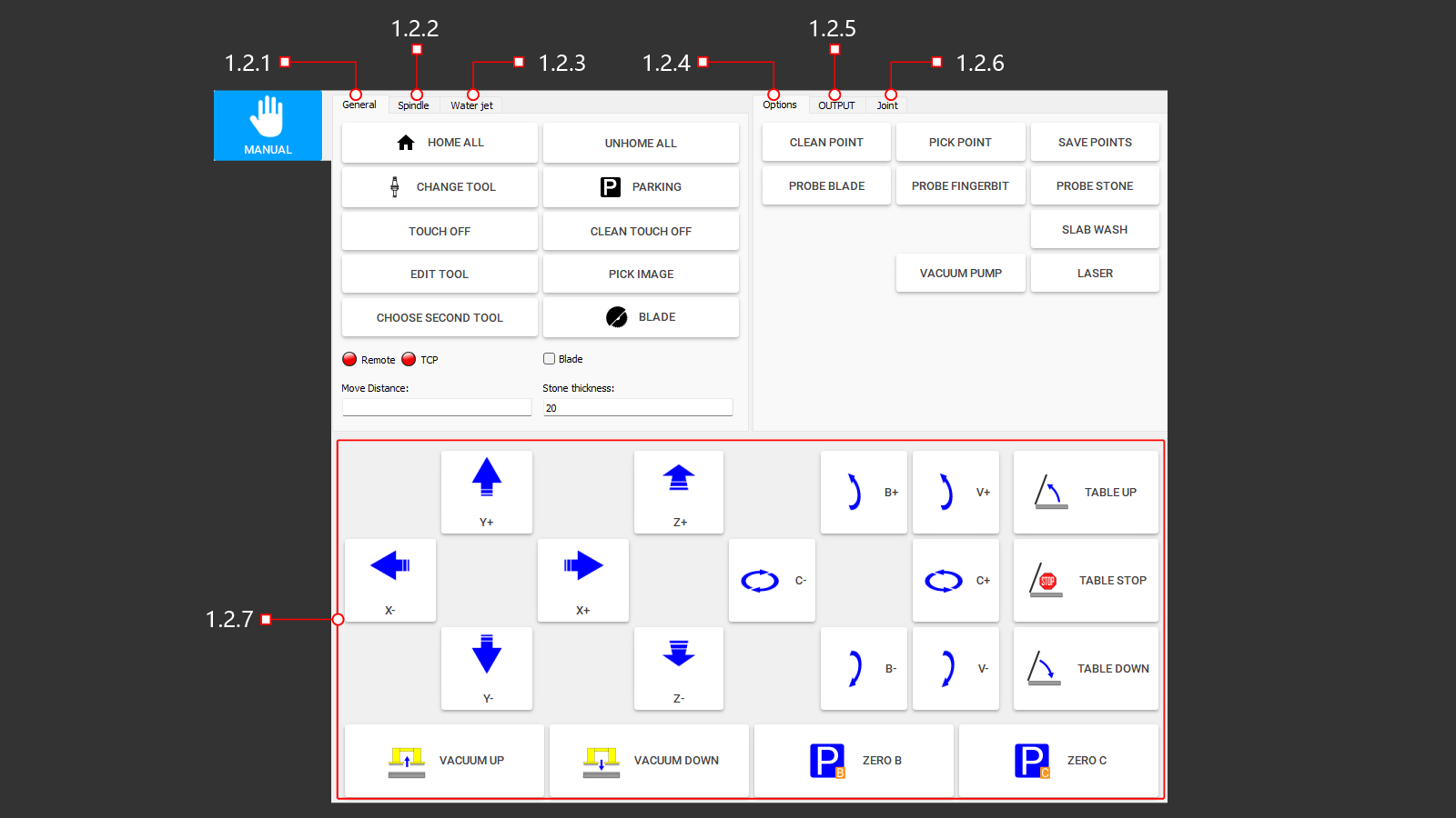
Figure 1.2: Manual page of the AitalMAC Application
The Manual Page provides direct access to machine operations and motion control. This interface enables operators to manually control various basic machine functions.
-
- Provides buttons for executing common machine functions.
-
- Activates spindle rotation according to the settings specified in the tool's database.
- Includes a button to change the spindle rotation direction (clockwise or counterclockwise), essential for tools requiring specific rotational directions.
-
- Controls for raising and lowering the water jet nozzle.
- Start and stop the high-pressure pump.
-
- Includes buttons for additional machine functions.
-
- Operates the main water supply valve.
- Activates auxiliary water systems.
- Controls cooling system water flow.
-
- Allows bypassing of axis limit sensors to move beyond axis limits.
- Note: This function should only be used with caution by authorized personnel.
-
- Enables movement along all axes.
- Operates table controls, such as lifting and lowering.
- Controls the vacuum lifter for slabs.
- Parks the machine along the B and C axes.
¶ 1.2.1 General
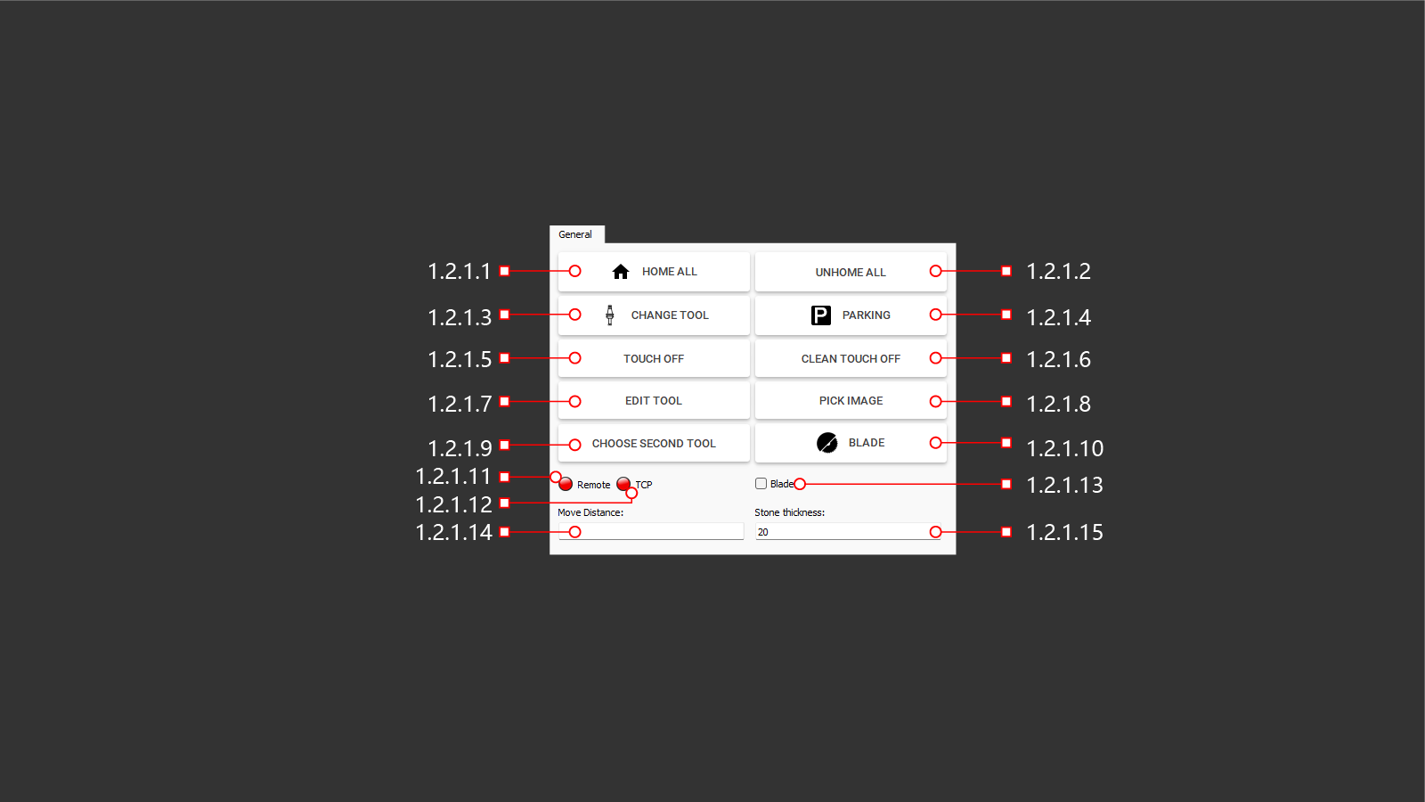
Figure 1.2.1: General tab within the manual page
The General control tab provides buttons for executing common machine functions, which will be described in detail in the following chapters.
¶ 1.2.1.1 Home All
The HOME ALL function moves all machine axes to their reference (home) positions.
- For machines equipped with motors featuring absolute encoders (which is the case for most AitalMAC machines), the home position is provisional.
- The provisional home position will be overwritten by the absolute encoder position when the Machine On button is pressed.
¶ 1.2.1.2 Unhome All
Clears the homed status of all machine axes.
¶ 1.2.1.3 Change Tool
Opens the tool list window, allowing the user to select and switch the active tool. This window can be used to set either the main or secondary tool, depending on the button used to access it. When accessed through "Change Tool," the selected tool is set as the main active tool. Note that the secondary tool option is only available on 5-axis saws.
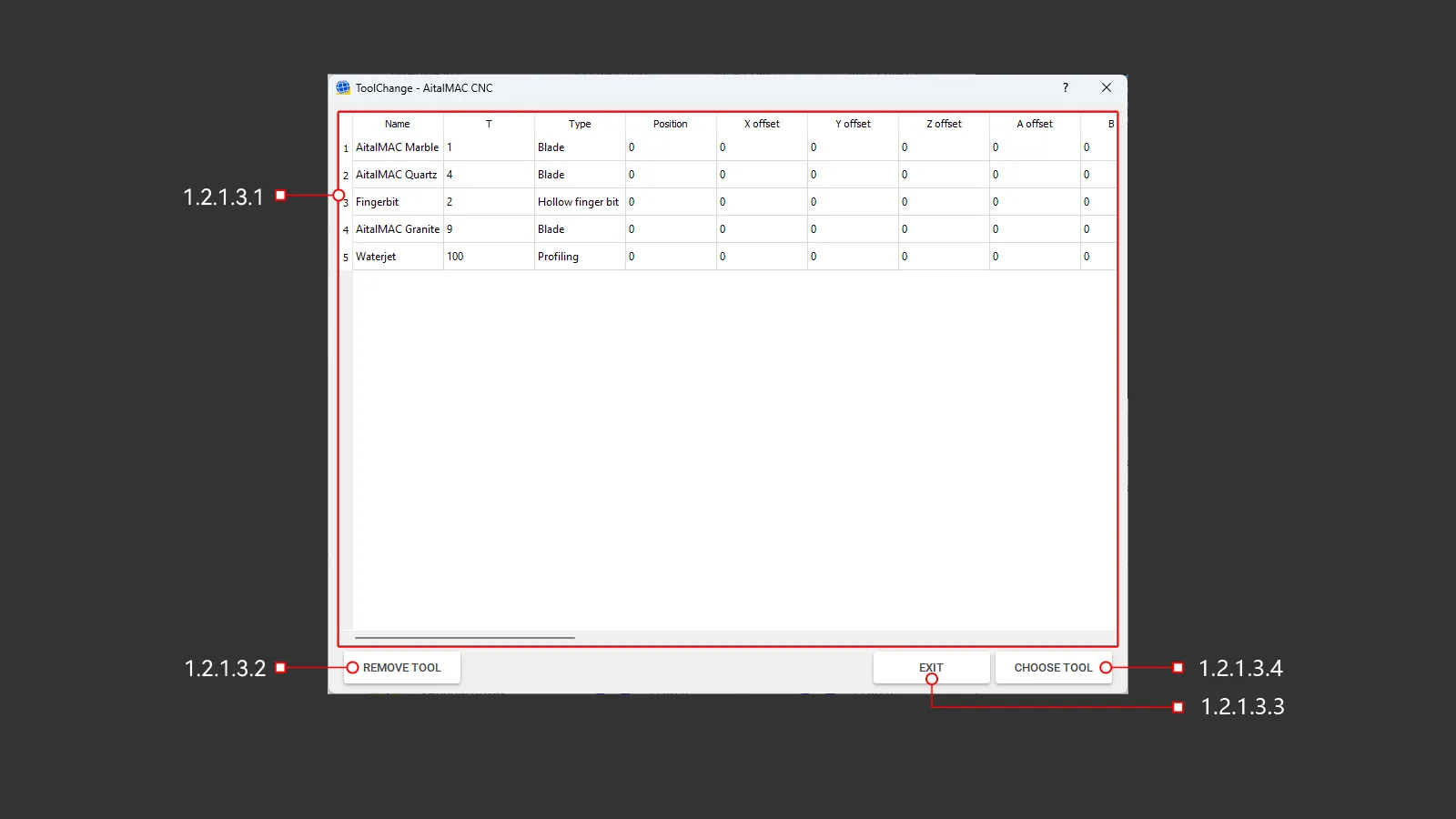
Figure 1.2.1.3: Tool change window
¶ 1.2.1.3.1 Tool List
A panel of tools stored in memory that the machine uses to operate.
¶ 1.2.1.3.2 Remove Tool
This button initiates a tool change operation to unload the currently used tool. On AitalMAC base model saws without automatic or manual tool change stations, the tool will simply be removed from memory. For machines with tool stations or positions, the automatic tool change routine will unload the current tool.
¶ 1.2.1.3.3 Exit
Closes the tool selection panel.
¶ 1.2.1.3.4 Choose Tool
This button activates the selected tool from the tool list for use on the machine. The tool list window can be accessed in two ways:
-
Selecting the main tool: Use Change Tool to open the tool list window and select the main active tool. On AitalMAC base model saws, the tool is loaded into memory. On machines with tool stations, the selected tool is automatically loaded or exchanged.
-
Selecting the secondary tool: Use Choose Second Tool (specific to 5-axis saws) to open the tool list window. The selected tool is set as the secondary tool, stored in memory, and displayed at the bottom of the application, separated from the main tool by a pipe symbol (|).
The designation of a tool as main or secondary depends entirely on how the tool list window is accessed.
¶ 1.2.1.4 Parking
This button moves the machine to a designated parking position as defined in the parameters. Parking is not always safe, particularly when the machine is engaged with the material, such as during a 45-degree miter cut. Always ensure the machine is in a safe state before initiating the parking operation.
¶ 1.2.1.5 Touch-off
Moves the machine origin reference point to the current tool position, effectively redefining the machine’s working coordinates.
If this action is performed by mistake and then confirmed, a blue line will appear in the 3D area to indicate the offset. It is advised to clear any accidentally applied touch-offs to prevent potential errors or unexpected behaviors.
¶ 1.2.1.6 Clean Touch Off
Clears and resets the current touch-off reference point.
¶ 1.2.1.7 Edit Tool
Opens a dialog to modify currently loaded main tool parameters.
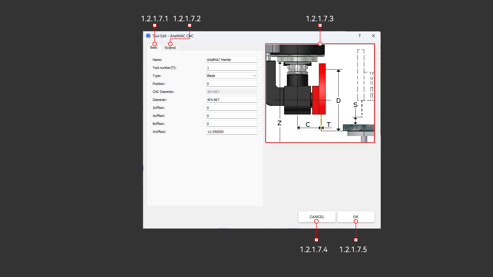
Figure 1.2.1.7: Edit tool window
Introduction to Tool Management
The tool management system in the AitalMAC application is inherited from AitekCAM, a CNC Stone Machining Center application initially developed for routing operations and later extended to include blade functionality. To maintain compatibility, AitalMAC still allows tools to be synced with AitekCAM. However, the way tool parameters are used differs significantly between the two systems. Additionally, programs post-processed by Pegasus CAD/CAM do not utilize the tool parameters defined within the AitalMAC application, as Pegasus relies on its own set of parameters for program execution.
In AitekCAM, parameters like tool types play a central role in defining the behavior of programs created within the CAM environment. These parameters influence the operation paths, machining logic, and other critical aspects of toolpath generation. In contrast, AitalMAC uses tool types primarily to manage conflicts between tools and operations. For example, in AitalMAC, users can only access the X-Y Cut page—designed specifically for blade tools—if the main loaded tool is of the blade type. In this context, tool types help ensure logical compatibility between operations and tool assignments rather than defining program behavior.
It is important to recognize that many of these parameters are influenced by the history of development. As a result, some parameters may appear unnecessary or out of place unless this historical context is considered. For instance, parameters like speeds and feeds are heavily utilized in AitalMAC, while others, such as safe position, are included solely for compatibility with AitekCAM, where they are still actively used. Understanding this distinction can help users better navigate and make sense of the tool management system in AitalMAC.
¶ 1.2.1.7.1 Basic

Figure 1.2.1.7.1: Basic parameters tab of the edit tool window
The Basic tab contains the essential parameters required to define a valid tool. These include the tool's name, type, number, position in the tool change sequence, diameter, and axis offsets.
¶ 1.2.1.7.1.1 Name
The Name field specifies the unique identifier for the tool. It serves as a label to easily recognize and distinguish the tool. The name should be descriptive enough to provide clarity about the tool's purpose or type (e.g., "Finber Bit 20mm" or "Saw Blade Marble 450mm"). Proper naming conventions ensure smooth operation, especially when managing multiple tools.
¶ 1.2.1.7.1.2 Tool Number (T)
The Tool Number (T) is a unique identifier used by the machine's logic to manage and reference tools during operations. The program ensures this number is unique. If a duplicate tool number is entered, an error will occur, and the program will automatically compile and assign the next viable unique number before saving the tool. This prevents conflicts and ensures accurate tool handling in the machining process.
¶ 1.2.1.7.1.3 Type
This field allows you to select the type of tool being used in the operation from a dropdown list. Available options include tools such as a drill, blade, finger bit, and others. The selected tool type is validated to ensure compatibility with the operation being performed. For instance, a probing operation requiring a finger bit will check that the second loaded tool is not a blade, as using an incorrect tool could lead to unexpected behaviors or errors.
If the wrong tool type is detected, the machine will stop and display an error message. This system safeguards against potential issues, maintaining safety and operational precision. Maintaining consistency between AitalMAC and Pegasus applications by matching tool types is strongly recommended, as future updates to AitalMAC may introduce similar restrictions, such as specific tool requirements for functions like drilling holes.
Tool Types in the Dropdown List:
- Profiling: Tools used by CNC Machining Centers to shape the edges of the stone. This type is included for AitekCAM compatibility purposes.
- Drill: Commonly used for creating cylindrical holes in materials. Drills are allowed as secondary tools in the AitalMAC application and can also be used in Pegasus to program drilling hole strategies, particularly for finishing concave corners that cannot be reached by a blade. It is recommended to maintain consistency by explicitly setting drills as such in both AitalMAC and Pegasus applications.
- Water Slot: Also known as calibration wheels, these tools are included for AitekCAM compatibility purposes. Operators will often set tools of this type due to their distinct appearance compared to a finger bit. While there are no strict limitations within the AitalMAC application, consistency with AitekCAM ensures smooth operation.
- Tap: Deprecated and maintained for legacy machines only, slated to be removed.
- Blade: Ensures compatibility for cutting tasks that require tools classified as "blade" type. The AitalMAC application enforces strict limitations, allowing only tools of this type to perform certain operations to ensure precision and safety. Properly selecting the tool type aligns the application’s operations with the intended tool usage, minimizing risks and maximizing efficiency. Although Pegasus and AitalMAC applications operate independently without strict integration, maintaining consistency in tool type settings across both systems is highly recommended. This practice simplifies workflows and ensures readiness for future updates and improvements to both applications.
- Finger Bit: Commonly used for CNC Machining Centers to cut sinks out, this tool type is also included for compatibility with AitekCAM rather than serving any specific function within the AitalMAC application. It is not recommended as the secondary tool for bridge saws, as the hollow finger bit tool type is better suited for such tasks, ensuring optimal compatibility and performance.
- Groove Bit: Maintained solely for compatibility with AitekCAM, as even the slope program within AitalMAC does not require this type of tool.
- Hollow Finger Bit: This is the correct type for the secondary tool for AitalMAC saw machines. Choose this type rather than the Finger Bit, as it is better suited for the type of processing performed by Pegasus, which runs steps in a spiral fashion.
¶ 1.2.1.7.1.4 Position
This setting specifies the position of the tool within the machine's magazine. On machines equipped with an automatic tool change function, the available positions are typically numbered, such as 1 to 27. These numbered positions correspond to the pockets in the magazine.
- Position 0: Reserved for manual tool changes. When a tool is assigned to Position 0, the machine will move to the manual tool change position and await user confirmation after the tool change is completed. This behavior is consistent regardless of whether the current and requested tool are both assigned to Position 0.
- Positions 1 to 27: These positions are used for automatic tool changes. If two tools are assigned to the same position, the tool change sequence is skipped because it is interpreted as stacked tools. This allows seamless transitions without requiring additional tool change operations.
- Positions 28 and Higher: These positions are also reserved for manual tool changes. However, unlike Position 0, if two tools share the same position number, the tool change sequence is skipped as it is interpreted as stacked tools.
It is important to note that Position 0 has unique behavior: the machine always moves to the manual tool change position and waits for user confirmation, even if the current and requested tool are both in Position 0. For positions beyond the magazine's automatic range (e.g., 28 and higher), the tool change sequence behaves similarly to stacked tools, skipping the sequence when tools share the same position number.
¶ 1.2.1.7.1.5 CNC Diameter
The CNC diameter is a view-only field showing the calculated diameter used for tool radius compensation (e.g., G41-G42), commonly applied when running tools along the edge of the material on CNC machining centers. It is derived as:
CNC Diameter = Diameter + (Removal × 2)
The Removal value, specified in the Extend tab, adds an offset to the tool radius to leave surplus material for subsequent tools in a multi-step grinding process. Each tool in the sequence progressively removes material, refining the surface left by the previous tool. Only the final tool, with no "Removal" offset, grinds the material to the programmed finished size using its actual measured diameter.
When probing the tool diameter on CNC machining centers, the machine will adjust both CNC and base diameters while keeping the Removal constant.
It is important to note that on 5-axis bridge saw machines, which predominantly use blade saw tools operating vertically and approaching the material from the top, removal offsets are not applied to depth. Removal compensation (via G41-G42) works exclusively on the XY plane, where the spindle approaches horizontally, as is typical for CNC machining centers. For 5-axis bridge saws, removal compensation is not applicable to either edge or depth, as the nature of the cutting process differs significantly from CNC machining centers.
¶ 1.2.1.7.1.6 Diameter
This is the actual, physical diameter of the tool as measured and entered by the operator when installing a new tool. The base diameter serves as the foundation for calculating the CNC diameter and represents the real dimensions of the tool itself. It ensures accurate toolpath calculations and material removal during machining processes.
For blade-type tools, the diameter can be probed by the machine. After a successful probing sequence, the measured diameter is automatically updated in the system, ensuring precise cutting operations and alignment.
¶ 1.2.1.7.1.7 Zoffset
This offset is applied along the Z axis using G43 and removed with G49, subtracting the tool’s offset from the current axis position. In most CNC machining centers with vertical spindles, tool length compensation occurs on the Z axis. However, on AitalMAC 5-axis bridge saws (and similar 5-axis machines), the tool length is compensated on the W axis, which runs parallel to the spindle’s axis.
¶ 1.2.1.7.1.8 Aoffset.
This offset applies to the A axis, which is typically not used on most AitalMAC machines. Keep it set to 0.
¶ 1.2.1.7.1.9 Boffset
This offset is associated with the B axis. On 5-axis bridge saws, where the B axis exists physically, Boffset is typically left at 0. However, on AitalMAC's CNC machining centers—which do not actually have a B axis—Boffset is repurposed for tool diameter probing.
During diameter probing, the offset designated as Boffset is temporarily applied on the Z axis to position the tool at the correct “probing height.” This probing height differs from the normal “working height,” which is managed by Zoffset. Therefore, Boffset does not serve as a tool-length offset during regular cutting operations; it is used solely to set the correct probing position for diameter measurement on machines without a physical B axis.
¶ 1.2.1.7.1.10 Woffset
Woffset is an offset applied along the W axis, which aligns with the main spindle axis where tools are mounted and acts as the tool length. This offset ensures accurate tool positioning on 5-axis machines by compensating for differences in tool geometry and mounting relative to the machine's pivot point.
For blade-type tools, the flange serves as the reference point for Woffset calculations. The flange provides a fixed and consistent mounting position, making it critical for precise alignment and operation.
Woffset is also applicable to all other tool types, including those not directly attached to the flange. In these cases, Woffset is calculated based on a theoretical flange position to maintain consistent functionality.
Pegasus software calculates Woffset for blade tools using the segment thickness and core thickness of the blade:
Woffset = (Segment Thickness - Core Thickness) / 2 + Core Thickness
This calculation assumes the blade is symmetrical. Operators must be aware that Pegasus sets Woffset automatically using this formula. For asymmetrical blades, operators must adjust parameters as though the blade were symmetrical to ensure proper machine operation.
Managing Woffset in Systems
- Without Tool Change Capability: On 5-axis machines without tool change support for CNC profiling tools, Pegasus software automatically manages Woffset, simplifying setup and ensuring precise cutting without manual intervention.
- With Tool Change Capability: On machines with tool change features, Woffset is managed within the AitalMAC application as the tool length offset. This applies to blades and other profiling tools, requiring operators to accurately set and maintain Woffset for reliable performance during tool changes.
Key Considerations
- Accurate Measurements: Measure segment and core thickness precisely.
- Symmetry Adjustment: Adjust parameters for asymmetrical blades, as Pegasus assumes symmetry.
- Software Integration: Identify whether Pegasus or AitalMAC handles Woffset in your workflow.
- Tool Consistency: Update Woffset settings for each tool type.
- Regular Calibration: Periodically verify Woffset settings to ensure accuracy.
Proper management of Woffset is essential for achieving high-quality and consistent cutting performance on 5-axis machines.
¶ 1.2.1.7.2 Extend
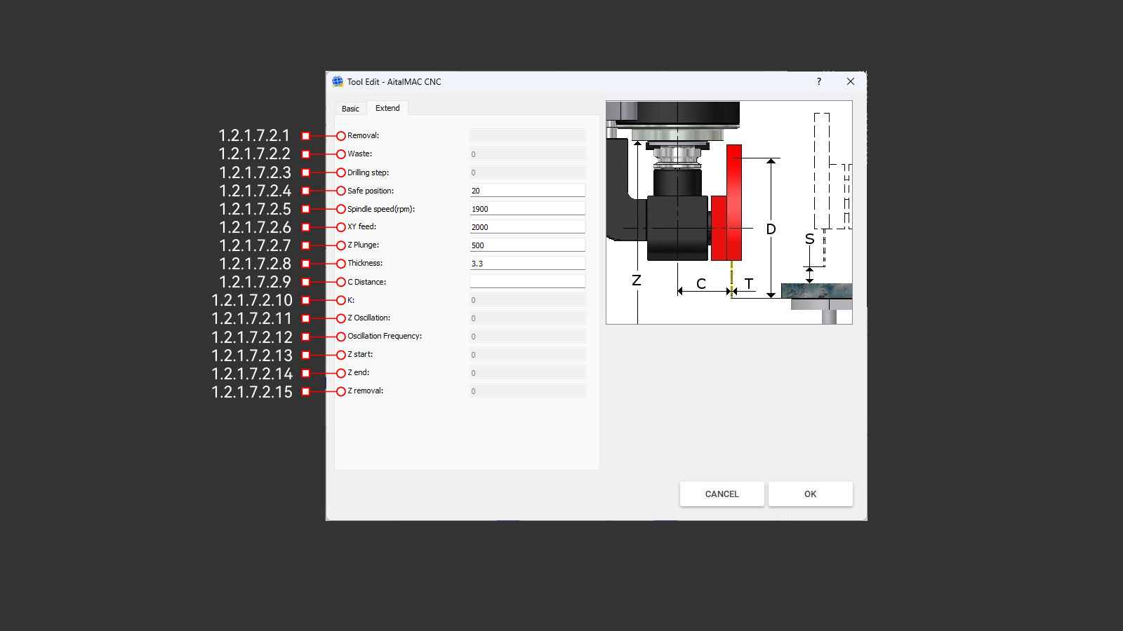
Figure 1.2.1.7.2: Extend parameters tab of the edit tool window
The Extend tab provides additional parameters for advanced tool setup and operation. While some of these parameters are optional, others—such as thickness, speed and feed settings—are essential for ensuring proper tool functionality.
¶ 1.2.1.7.2.1 Removal
The "Removal" is a crucial parameter that defines the additional offset added to the tool radius during CNC operations. This value is entered in the Extend tab and directly influences the calculation of the CNC diameter:
CNC Diameter = Diameter + (Removal × 2)
The primary purpose of the Removal is to leave surplus material for subsequent tools in a multi-step grinding process. Each tool in the sequence removes a layer of material, refining the surface left by the previous tool. This ensures that every tool can perform its task effectively, leading to a smooth and precise finish.
On CNC machining centers, removal is compensated by G41 and G42, which operate in the XY plane with the spindle vertical. This allows accurate edge compensation during machining. However, on 5-axis bridge saw machines, where blade tools approach the material from the top, removal does not influence depth adjustments.
Only the final tool in a grinding tool set operates without a Removal offset, using its exact diameter to achieve the programmed finished size. Proper configuration of the Removal parameter is essential for achieving precise machining results and maintaining consistent surface quality.
Availability: Removal is exclusively enabled for Profiling, Finger Bit, and Water Slot tool types. For all other tool types, this parameter remains inactive (greyed out).
¶ 1.2.1.7.2.2 Waste
This parameter is specific to tools used in CNC machining centers and exists solely for AitekCAM compatibility purposes. "Waste" is used by AitekCAM to generate programs that compensate for tool wear by adjusting the tool diameter between toolpath executions. This ensures that wear is accounted for before each new cycle.
In contrast, "Dynamic Wear" operates incrementally during the execution of a toolpath while the tool is in contact with the stone, allowing for more precise and adaptive compensation. While "Waste" is still present for legacy support, it has been largely replaced by "Dynamic Wear" in modern workflows.
Availability: Waste is exclusively enabled for Profiling, Finger Bit, and Water Slot tool types. For all other tool types, this parameter remains inactive (greyed out).
¶ 1.2.1.7.2.3 Drilling Step
This parameter is maintained for AitekCAM legacy compatibility and specifies the peck drilling depth used in generating peck drilling programs with drill tools.
Availability: Drilling Step is exclusively enabled for drill-type tools. For all other tool types, this parameter remains inactive (greyed out), as it is not applicable to them.
¶ 1.2.1.7.2.4 Safe Position
This parameter is included solely for compatibility with AitekCAM and does not directly operate within the AitalMAC application. It defines the distance of the tool above the material used during rapid movements within the generated program. Safe Position ensures that the tool clears the material safely when moving between machining operations, preventing collisions and optimizing workflow.
For AitalMAC Manual and Semi-Auto operations, the equivalent parameter is the Safety above the stone parameter, which is located in the Parameters page, not within the tool edit window where Safe Position is configured. This distinction ensures clarity in how these parameters are applied within their respective contexts.
¶ 1.2.1.7.2.5 Spindle Speed (RPM)
This parameter specifies the spindle revolutions per minute (RPM) and is valid in both AitalMAC and AitekCAM applications when using this tool. The spindle speed should be set considering the tool diameter, the material to be cut, and the recommendations provided by the tool manufacturer. Adhering to the recommended speed ensures optimal performance and prevents unnecessary wear or damage to the tool and material.
¶ 1.2.1.7.2.6 XY Feed
This parameter is valid in both AitalMAC and AitekCAM applications and specifies the feed rate in units per minute (units/min) that the tool will use while cutting the material in the X and Y directions. It is recommended to follow the feed rate suggested by the tool manufacturer, considering the material being processed. This parameter has no viability for drill tool type.
¶ 1.2.1.7.2.7 Z Plunge
Specifies the feed rate along the Z-axis during material entry. Set to 10%-15% of the XY Feed rate, with adjustments based on tool diameter, material properties, and manufacturer specifications. Ensures safe, effective plunging. Applicable in both AitalMAC and AitekCAM applications.
¶ 1.2.1.7.2.8 Thickness
Exclusive to blade-type tools, this parameter is valid in both AitekCAM and AitalMAC applications. It is used in semi-automatic processing to precisely adjust machine movements between cuts, compensating for blade thickness. Only enabbled for tools of Blade-tool type.
¶ 1.2.1.7.2.9 C Distance
The C Distance parameter does not function within the AitalMAC application. It was originally exclusive to AitekCAM for blade tools, where it served as a basic kinematics pivot offset for 4-axis machines. This parameter is now deprecated in AitekCAM and slated for removal from AitalMAC in future versions. Users of AitalMAC versions newer than this documentation may no longer see this parameter.
¶ 1.2.1.7.2.10 K
The K parameter is exclusive to Tap-tool type, which are slated for removal. This parameter may no longer be present in AitalMAC application versions released after the date of this documentation.
¶ 1.2.1.7.2.11 Z Oscillation
The Z Oscillation parameter is not used in the AitalMAC application and is exclusive to AitekCAM. It is valid only for Profiling and Finger Bit tools and specifies the wave height for oscillating toolpaths. When set to a non-zero value, it creates a wave-like motion along the Z-axis. The parameter can also take negative values, causing the entire wave to remain below the default working height.
This feature is used to ensure consistent tool wear along the entire length or to minimize visible lines in the material after processing.
¶ 1.2.1.7.2.12 Oscillation Frequency
Oscillation Frequency is closely related to the Z Oscillation parameter and determines the frequency of the wave generated when Z Oscillation is non-zero. The frequency is defined as half the wavelength of the wave. This parameter just like "Z Oscillation" is not used in the AitalMAC application and is exclusive to AitekCAM, applicable only to Profiling and Finger Bit tools.
¶ 1.2.1.7.2.13 Z Start
Exclusive to AitekCAM and only applicable to Groove Bit tool type, this parameter defines the starting height offset added to the tool's default working height. A negative value causes the tool to plunge deeper into the material. Groove Bits are designed for single-line segment paths in AitekCAM, enabling sloping linear paths when used in conjunction with Z End.
¶ 1.2.1.7.2.14 Z End
Exclusive to AitekCAM and only applicable to Groove Bit tool type, this parameter defines the ending height offset added to the tool's default working height. Like Z Start, a negative value causes a deeper plunge into the material. Together with Z Start, it facilitates the creation of sloping linear paths for single-line segment operations.
¶ 1.2.1.7.2.15 Z Removal
Exclusive to AitekCAM and only applicable to Groove Bit tool type, Z Removal is an additional offset applied to both Z Start and Z End. It simplifies creating a series of tools with incremental depths, where each subsequent Groove Bit plunges deeper. As Z Removal decreases, the tool plunges further into the material, allowing for precise control over depth. A Z Removal value of 0 aligns the start and end heights exactly with Z Start and Z End offsets.
¶ 1.2.1.7.3 Reference Image
This image provides a visual representation of key parameters in a standard format, helping users understand their purpose and functionality. Each tool type has its own dedicated image, serving as a guide for easier parameter interpretation.
¶ 1.2.1.7.4 Cancel
This button discards the last changes made to the tool settings and closes the tool edit window.
¶ 1.2.1.7.5 OK
This button saves the last changes made to the tool settings and closes the tool edit window.
¶ 1.2.1.8 Pick Image
Opens a window that uses the machine's camera to capture an image of the workbench and workpiece. It is recommended to park the machine before opening this window to ensure safe operation.
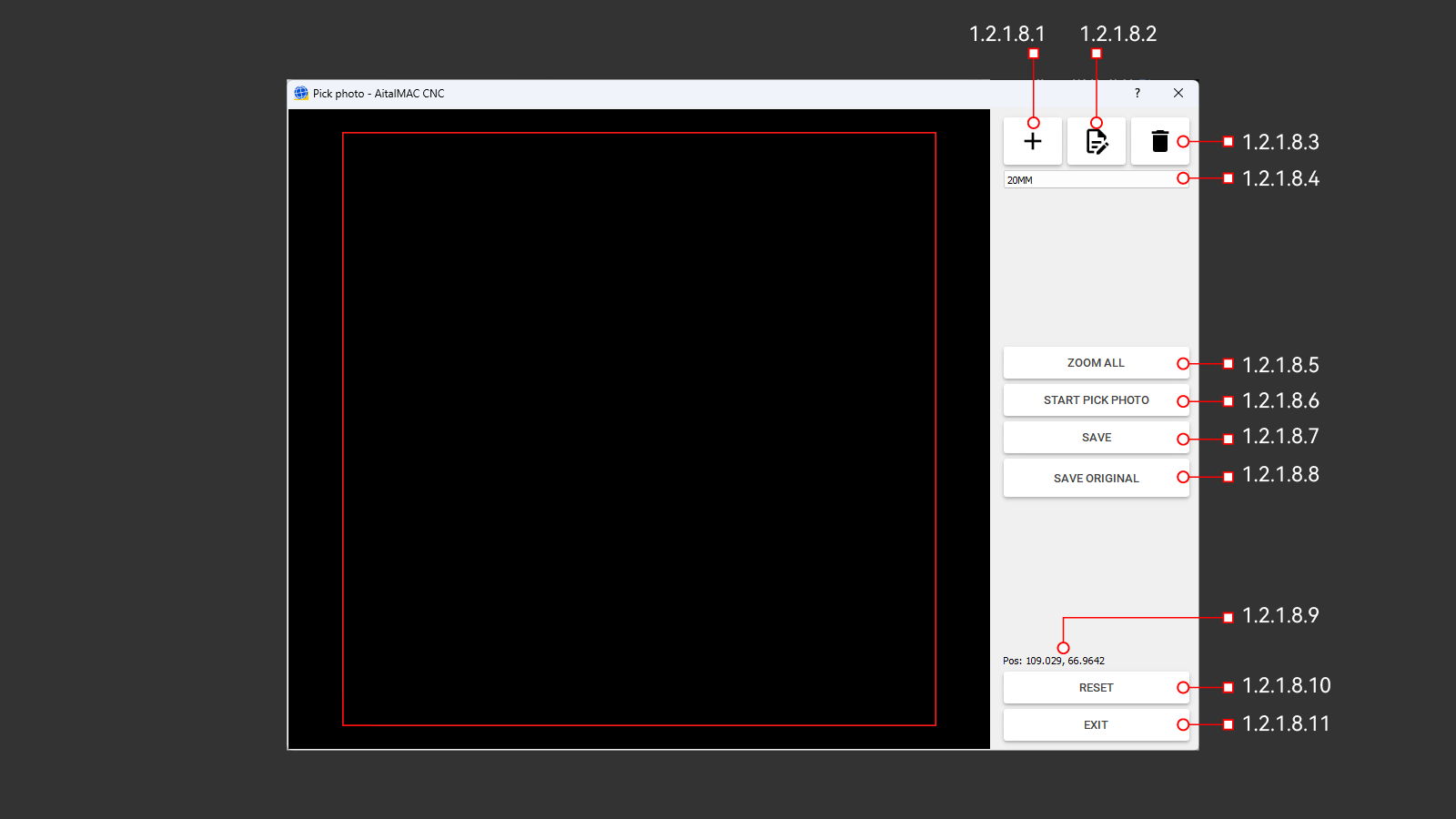
Figure 1.2.1.8: Pick Image window
¶ 1.2.1.8.1 Add
Opens a dialog to create a new camera configuration by entering a name. After confirmation, the configuration is saved as an empty, unparametrized setup and becomes the active configuration.
¶ 1.2.1.8.2 Edit
Opens a dialog to rename the active camera configuration. Changes can be confirmed or canceled to keep the original name.
¶ 1.2.1.8.3 Delete
Deletes the active camera configuration. Deletion is not allowed if it is the only configuration available.
¶ 1.2.1.8.4 Camera Configuration Selection
A dropdown list displaying all available camera configurations. AitalMAC supports managing multiple configurations, typically organized by material thickness. This can be avoided by using instead the camera configurations manager in Pegasus CAD/CAM, allowing the use of a single general configuration in the AitalMAC application while Pegasus handles specific adjustments for varying thicknesses. As of this document's writing, this setup is common on most AitalMAC brand machines.
¶ 1.2.1.8.5 Zoom All
Clicking this button adjusts the view to fit the entire photo within the view area.
¶ 1.2.1.8.6 Start Pick Photo
This button captures a photo of the material on the machine workbench. The machine must be powered on, and the camera must be properly connected and identified. After opening the Pick Image window, the user must wait for the countdown displayed on the button to ensure proper connection.
Clicking the button raises the Z-axis and moves the machine to the designated position to take the photo. Before using this function, ensure the machine is in a safe state, ideally parked, which can be done from the Manual page. This precaution prevents any unintended movements or collisions.
¶ 1.2.1.8.7 Save
Opens the Windows Save File dialog to save the image captured by the camera. The saved image is typically scaled to 1 pixel per mm based on the active camera configuration.
¶ 1.2.1.8.8 Save Original
Opens the Windows Save File dialog to save the raw image captured by the camera without applying any perspective or dimensional corrections. This option, available only for DSLR camera setups, allows users to save the original image for comparison with the corrected version to assess any potential deterioration in quality.
¶ 1.2.1.8.9 Pos
Displays the current machine X and Y positions. This feature is intended for debug purposes only.
¶ 1.2.1.8.10 Reset
This button reboots the camera system to reinitialize it when it becomes unresponsive. Pressing "Reset" closes the "Pick Image" window and initiates the reboot process. The AitalMAC application then enforces a 1-minute wait before allowing reentry to the "Pick Image" window.
Use this button if the camera displays a black picture or connection errors specific to the camera system occur. After the minute elapses, manually click the "Search" button 🔍, located in the bottom toolbar, to re-establish the connection and verify connectivity.
¶ 1.2.1.8.11 Exit
Closes the "Pick Image" window.
¶ 1.2.1.9 Choose Second Tool
This button opens the tool list window to select and switch the current secondary active tool. This functionality is specific to 5-axis saws.
The secondary tool complements the primary saw blade tool, typically mounted alongside it on the spindle. It can be a Hollow Finger Bit, a drill, or a waterslot/calibration tool type. Secondary tool selection is specific to the AitalMAC application, where certain operations validate the tool type. This selection has no impact on Pegasus CAD/CAM. For example, the Probe Fingerbit operation in AitalMAC will not function if a blade-type tool is set as the secondary tool. The secondary tool is displayed at the bottom of the application, alongside the primary tool, separated by a pipe symbol (|).
¶ 1.2.1.10 Blade
This button toggles the spindle on and off, starting at the main tool's speed(RPM) or, if the B axis is at position 0, the second tool's speed(RPM). The spindle speed can also be adjusted manually using the spindle override slider.
¶ 1.2.1.11 Remote Status Light
A status light on the monitor shows remote control status: red means inactive, green means active.
¶ 1.2.1.12 TCP Status Light
The TCP (Tool Center Point) status is exclusively relevant on the Manual Page of the AitalMAC application for 5-axis saw machines. The status light switches from red (inactive) to green (active) when the physical TCP switch on the machine panel is turned on.
With TCP inactive (red), axis movements and rotations are direct: linear axes move along their respective directions, and rotations affect only the machine parts directly connected to the motor for each axis.
When TCP is active (green), movements are tool (saw blade) related. Linear movements follow the blade's orientation, meaning if the tool is angled, the machine moves linearly along that angle. If the tool rotates 180 degrees, directional controls may feel reversed; for example, pressing the right button might move the machine left. While initially counterintuitive, this mode allows precise manual cutting at any angle. To simplify navigation, imagine the table moving under the stationary tool rather than the head moving.
Rotations with TCP active occur around the blade's tip, which serves as the center of rotation. This ensures that the cutting edge remains consistent in position during adjustments, preventing the tool from shifting to a different spot as it would with TCP off. Moving the B axis, which rotates the tool tip around the Y axis, can be counterintuitive. Rotating B so that the blade comes down will actually move the machine up. Most users lift Z to its maximum before attempting B rotation, which will not leave enough space and will trigger B limit warnings or errors. To avoid this, keep the Z axis lower during B movements or perform these movements with TCP off.
¶ 1.2.1.13 Blade Thickness Check
This check mark enables the blade thickness to be included in movements perpendicular to the blade's cutting direction (Y+/Y-) exclusively when TCP is on. While not always required, it is essential when transitioning between cuts where the cutting side of the blade changes. For example, when switching from cutting the front side (using the back of the blade) to cutting the back side (using the front of the blade), the blade thickness must be included to ensure the piece is cut to the correct size.
In some cases, such as cutting pieces with consistent cutting sides (e.g., an L-shaped piece where both cuts use the same side of the blade), including the blade thickness will result in incorrect dimensions. This flexibility is why the blade thickness check is optional rather than a persistent feature.
Example Usage:
- To cut a piece 600mm wide:
- Perform the first front cut and raise the blade out of the stone.
- Enter "600mm" in the distance input field.
- Enable the blade thickness check.
- Move in the Y+ direction; the CNC will calculate and move 600mm plus the blade thickness automatically, as the blade check toggle is enabled.
- Complete the second cut to achieve a piece exactly 600mm wide.
¶ 1.2.1.14 Move Distance
Input field for the incremental distance for manual movements. When a value is entered in this field, and the user clicks any axis direction movement button, the machine will move incrementally in the direction indicated by the button for the specified amount.
If the entered distance exceeds the machine's limits, the machine will move to the limit instead. Additionally, if the blade thickness check is enabled, the blade thickness will be added to the movement. Incremental movements work with both TCP OFF and ON, but the blade thickness is only added when TCP is ON. Note that with TCP OFF, the machine will move differently, as described in the TCP chapter.
¶ 1.2.1.15 Stone Thickness
This input field allows the user to specify the thickness of the material (such as stone) on the workbench. The thickness can either be manually entered or automatically updated using the Probe Stone function, which runs a probing sequence to determine the material's thickness.
The stone thickness is utilized in both manual and semi-automatic functions. It plays a critical role in calculating safe rapid movement heights and determining the appropriate height for approaching and cutting the material with proper feed rates. Accurate input of the stone thickness ensures efficient and safe operations. Incorrect thickness input may cause the tool to plunge into the material at rapid feed, potentially damaging both the material and the tool.
Note: This parameter is specific to AitalMAC operations and does not apply to Pegasus post-processed programs.
¶ 1.2.2 Spindle
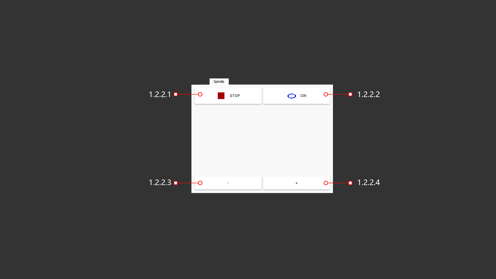
Figure 1.2.2: Spindle control functions tab
The Spindle tab provides direct controls for testing the spindle independently of tool setup. These controls are intended for diagnostic purposes.
¶ 1.2.2.1 Stop
Halts the spindle immediately, regardless of how it was started.
¶ 1.2.2.2 CW (ClockWise)
Enables the spindle to rotate clockwise, which is the standard rotation direction for AitalMAC machines.
- Orientation Note: On 5-axis saws, the spindle is typically horizontal and points toward the operator. From the operator's perspective, the blade appears to spin counter-clockwise, but from the spindle's perspective, it rotates clockwise.
- Compatibility: AitalMAC uses right-threaded spindles (unlike the traditional left-threaded spindles in the stone industry) to maintain consistency with CNC work centers. This allows for interchangeable tools and versatile machine functionality.
- Operation: This button must be pressed to initiate rotation. Speed adjustments (+/- buttons) will not function unless a direction is specified.
¶ 1.2.2.3 - (spindle Speed Decrease)
Reduces spindle speed by 100 RPM per click. Requires a rotation direction to be specified first.
¶ 1.2.2.4 + (spindle Speed Increase)
Increases spindle speed by 100 RPM per click. Requires the spindle to be initiated in a specified direction (set with the CW button).
¶ 1.2.3 Water Jet
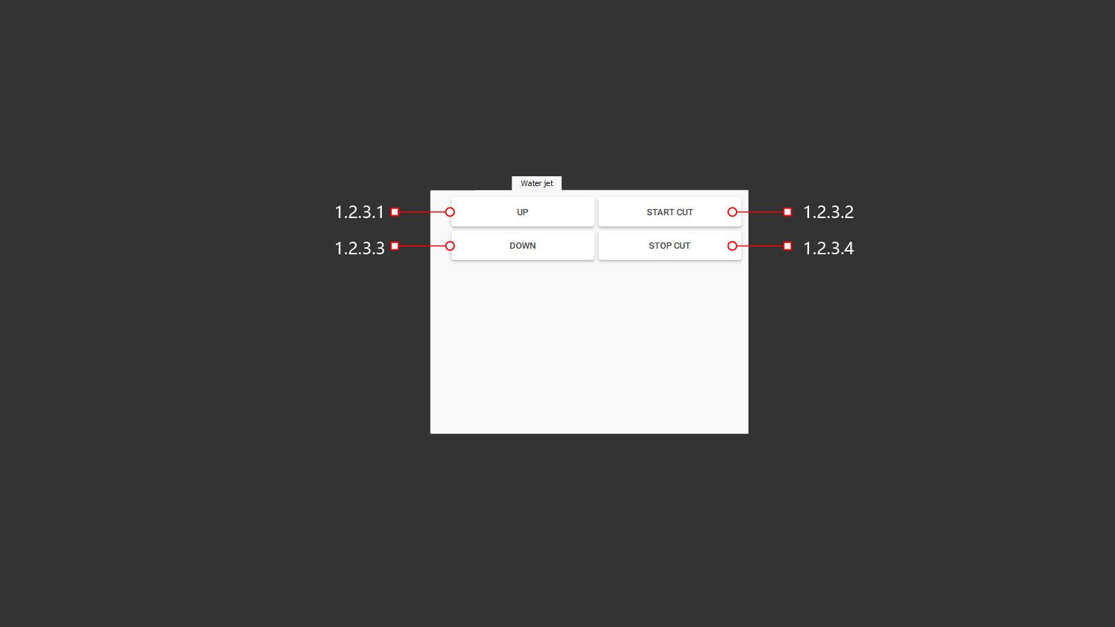
Figure 1.2.3: Water Jet control functions tab
The Water Jet tab provides the primary functions for manually operating the waterjet cutting head. It is typically used for troubleshooting or testing before running automatic programs.
¶ 1.2.3.1 Up
Lifts the waterjet cutting head when clicked. Once lifted, the machine switches back to the previously active kinematics configuration.
¶ 1.2.3.2 Start Cut
Initiates the waterjet pump. When pressed, the pump begins building up pressure to the value set in the parameters page. Simultaneously, the garnet valve opens to allow garnet flow into the cutting head. After a predefined delay, also set in the parameters page, the waterjet is fully operational and ready to cut.
¶ 1.2.3.3 Down
Lowers the waterjet cutting head. The head will only descend if there is sufficient space; otherwise, the machine will display a warning about inadequate clearance, and the descent will be blocked.
When the waterjet cutting head is lowered, the machine automatically references its movements to the waterjet tip, regardless of the TCP switch or light status. This ensures precise control of cutting operations. The waterjet kinematics (Kins 1) remain active until the head is lifted again.
¶ 1.2.3.4 Stop Cut
Halts the waterjet pump. Pressing this button closes the sand supply valve and gradually slows the pump to a complete stop. This delay allows the system to flush sand from the pipes and ensures a safe and smooth shut-off, preventing potential damage.
¶ 1.2.4 Options
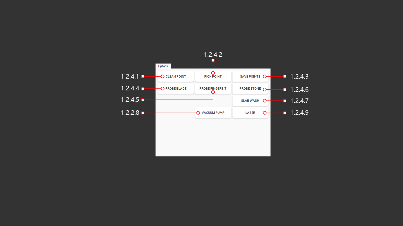
¶ 1.2.4.1 Clean Point
Clears all previously stored points from memory and removes them from the 3D preview, ensuring a clean workspace for recording new points.
¶ 1.2.4.2 Pick Point
Records a new point in memory and marks it as a red cross in the 3D preview. The point corresponds to the laser pointer's position, with its offsets relative to the tool configured in the parameters page. For 5-axis saws, orient the C axis at C -90 (parking) with the blade pointing forward to ensure accurate retrieval and alignment.
¶ 1.2.4.3 Save Points
Opens the Windows save dialog to save all stored points as a DXF file. Each point is represented as a circle in the DXF file, with its radius specified in the parameters page. This file is suitable for further processing or program creation.
The stored points have versatile applications, including:
- Material Position Reference: Use the points to locate the material's position within the machine or any reachable point in the working area.
- Realignment for Processing: Align the machine with pre-cut material for additional processing steps.
- Digitalizing Physical Templates: Record multiple points along the shape of a physical template placed on the machine workbench. These points can be connected in CAD software to recreate the shape digitally.
Note: The stored points adhere to the machine's coordinate system. If the laser pointer marks a point, the machine tool will process at that position—not the laser pointer.
¶ 1.2.4.4 Probe Blade
This button initiates the diameter check for the main blade tool mounted on the spindle. The machine moves to the designated probe position and carefully lowers toward the probe until the blade makes contact, allowing it to measure the blade's diameter. The measured value is then recorded in the tool's settings.
All subsequent manual and semi-automatic functions that utilize the blade automatically adjust for this measurement. Corrections include the safe rapid movement height, the height required to reach the material, and the height to approach the workbench surface. Since these height adjustments are calculated based on the blade's radius, any changes to the diameter will result in only half as much change in the corresponding height values. These adjustments ensure safe and precise machine operations.
Note: It is advised to initiate the probe blade sequence from the parking position, or at least from a position where it is safe to lift the blade straight up, to avoid collisions or unsafe movements.
¶ 1.2.4.5 Probe Fingerbit
The button for checking the length of the installed milling cutter is located on the machine. After checking, the actual length of the cutter will be recorded in the tool parameters, and the machine will execute commands with the necessary adjustments. This ensures that the depth of immersion into the worktable and the beginning of milling are accurate, based on the thickness of the material being processed. This helps to avoid collisions and incorrect cuts, as well as any collisions with the material being machined.
¶ 1.2.4.6 Probe Stone
Button for using a probe to study the thickness of the material to adjust the operation of the machine according to the program and in manual mode.
A button to check the thickness of the material used. Thickness adjustment is necessary for proper cutting with a blade and a water jet at an angle from 1° to 57° in order to maintain the overall dimensions of the part. For milling, this is the redefinition of the safety zone and the calculation of the material milling steps.
¶ 1.2.4.7 Slab Wash
Turning on the watering can to clean the material from dirt
A button to turn on the water pressure cleaning system. This is necessary to use a vacuum lift for flat material weighing up to 500 kg. Before using the vacuum suction cups, the operator washes the contact points of the suction cups with the material.
¶ 1.2.4.8 Vacuum Pump
A button to turn on the vacuum pump. When the pump is turned on, a suction force is created on the suction cups to lift and then move the material.
¶ 1.2.4.9 Laser
The laser line corresponds to the direction of the cutting blade and helps the operator to adjust the cutter to cut the material at the desired location.
¶ 1.2.5 Output
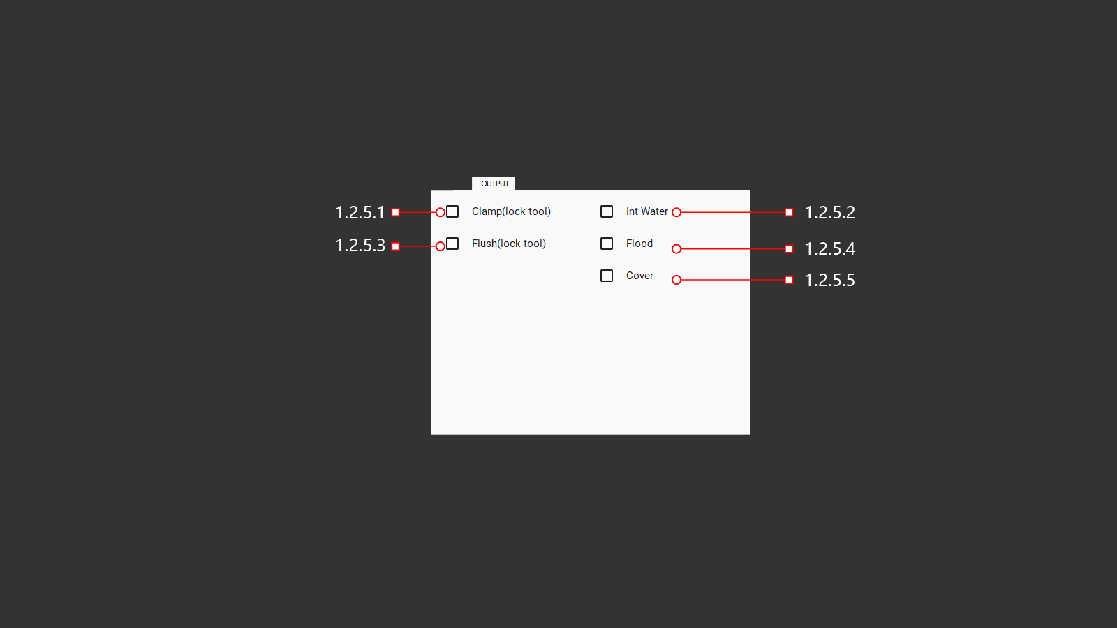
A tab with output signals for various machine functions. The operator can use these signals to check and adjust settings.
¶ 1.2.5.1 Clamp (lock Tool)
Button for fixing the tool clamp (for spindles with automatic changer)
¶ 1.2.5.2 Int Water
Turning on the water to cool the tool through the central hole. Water is supplied through the center of the spindle with air supply to clean the tube after the water is turned off. When turned on, the operator can adjust the air pressure for the required balance.
¶ 1.2.5.3 Flush
Button for cleaning the tool clamp (for spindles with automatic changer)
¶ 1.2.5.4 Flood
Turning on all instrument cooling systems: these are the internal and external cooling supplies. They help the operator to adjust the cooling direction of the tool to produce high-quality work and results.
¶ 1.2.5.5 Cover
Захват конуса инструмента.
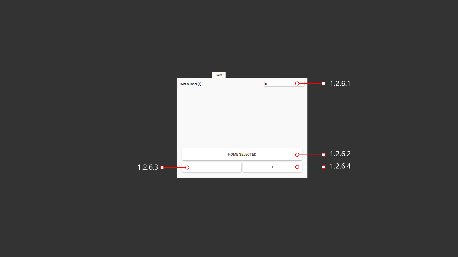
¶ 1.2.6 Joint
The servomotor control tab allows you to exceed the limits in case of an error or if the operator needs to control each axis of the machine individually.
¶ 1.2.6.1 Joint Number (X)
When clicked, a tab will open with a selection of the servo motor to control. In the case of the Y-axis, the movement must be carried out with extreme care, because the Y-axis controls two servomotors.
¶ 1.2.6.2 Home Selected
A button that will move the axes back to their home position based on the parameters set in the machine, using axis position limit sensors.
¶ 1.2.6.3 -
A button to move the selected machine axis in the negative direction. Move with a small feed and be careful.
¶ 1.2.6.4 +
A button to move the selected machine axis in a positive direction. Move with a small feed and be careful.
¶ 1.2.7 Control
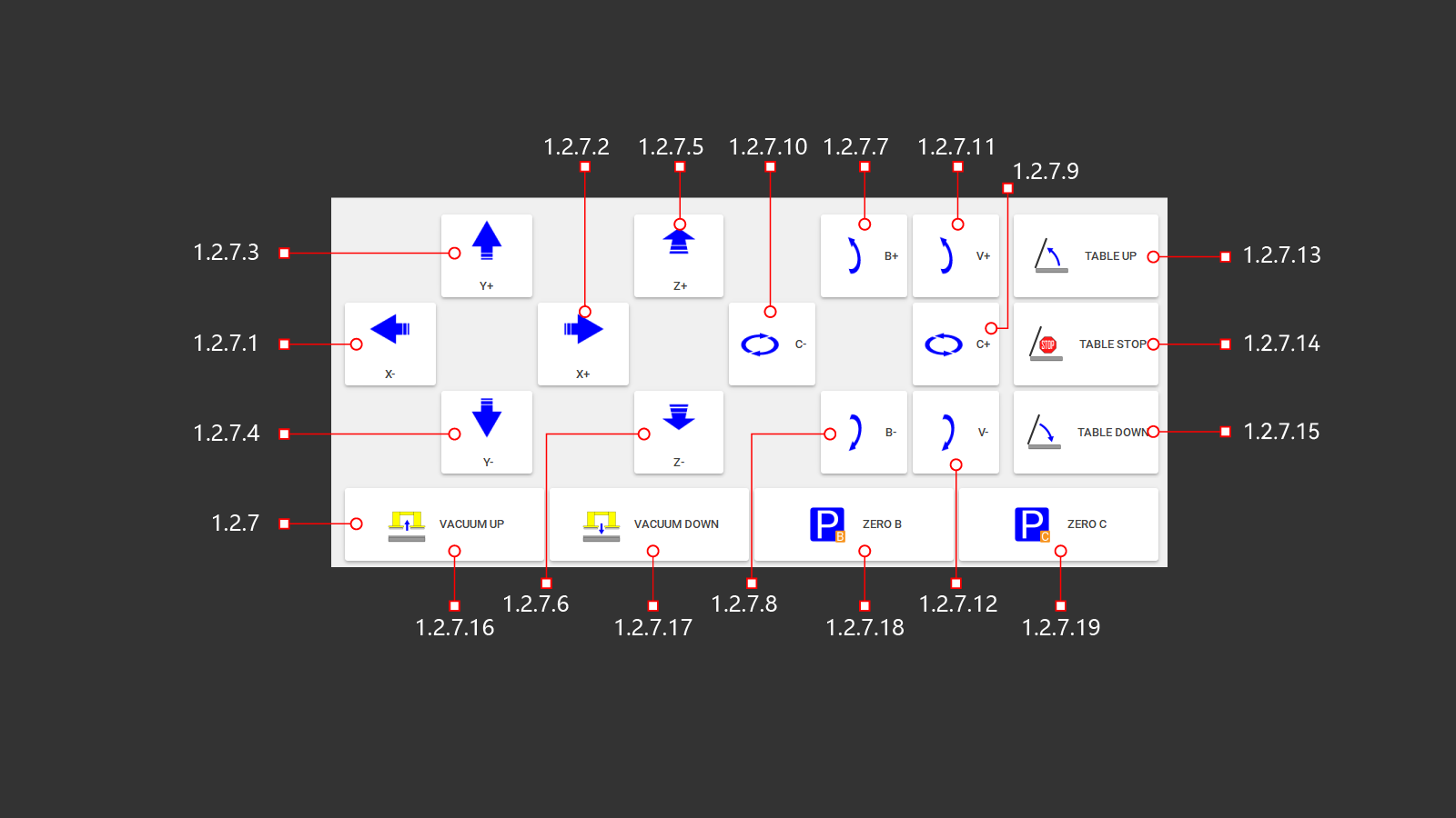
The operator's manual controls the machine. The operator can adjust the position of the selected cutting tool and perform necessary cutting operations. It is important to raise the work table for convenient loading of processed material and lower it with the material for further work. The operator has access to vacuum suction cups to move the material manually. There is an ability to return the C and B axes to their home positions after moving them manually.
¶ 1.2.7.1 X+
Controls the movement of the machine along the coordinate axes in the selected direction.
¶ 1.2.7.2 X-
Controls the movement of the machine along the coordinate axes in the selected direction.
¶ 1.2.7.3 Y+
Controls the movement of the machine along the coordinate axes in the selected direction.
¶ 1.2.7.4 Y-
Controls the movement of the machine along the coordinate axes in the selected direction.
¶ 1.2.7.5 Z+
Controls the movement of the machine along the coordinate axes in the selected direction.
¶ 1.2.7.6 Z-
Controls the movement of the machine along the coordinate axes in the selected direction.
¶ 1.2.7.7 B+
Control of spindle tilt along coordinate axes in the selected direction.
¶ 1.2.7.8 B-
Control of spindle tilt along coordinate axes in the selected direction.
¶ 1.2.7.9 C+
Control of spindle rotation along coordinate axes in the selected direction.
¶ 1.2.7.10 C-
Control of spindle rotation along coordinate axes in the selected direction.
¶ 1.2.7.11 V+
Controlling the tilt of the water jet module along the coordinate axes in the selected direction.
¶ 1.2.7.12 V-
Controlling the tilt of the water jet module along the coordinate axes in the selected direction.
¶ 1.2.7.13 Table Up
A button to raise the desktop. The hydraulic pump is turned on and the distribution valve directs the oil into the cylinders to start the lifting mechanism of the worktable.
¶ 1.2.7.14 Table Stop
A button to stop the operation of the lifting and lowering mechanism of the desktop. After pressing, the hydraulic pump turns off and the hydraulic distributor switches to the neutral position.
¶ 1.2.7.15 Table Down
The button for lowering the desktop. The hydraulic pump is turned on and the distribution valve directs the oil into the cylinders to start the lowering mechanism of the working table.
¶ 1.2.7.16 Vacuum Up
The operator uses a button to activate the vacuum suction cups to move the material. Once activated, the system lowers the vacuum suction cups into their working position using pneumatic cylinders.
To visualize the operation, a photo of the material on the desktop is displayed on the screen. This allows the user to see where the suction cups are relative to the material and the table. Depending on the vacuum generation system in use, the vacuum pump or air supply to the vacuum generators may be turned on.
Material movement operations should be carried out with a low rate of movement along the desired axes.
¶ 1.2.7.17 Vacuum Down
The button is necessary for the operator to put the lifted object in the moved place on the desktop. After pressing, the machine will automatically lower the material onto the worktable, the vacuum generation system will turn off, this is turning off the vacuum pump or turning off the air supply to the vacuum generators. The machine will lower the material and raise the vacuum system to standby mode using pneumatic cylinders.
¶ 1.2.7.18 Zero B
After pressing this button, the machine will move along the selected axis B to the position sensor and return to the starting position relative to the set parameters.
¶ 1.2.7.19 Zero C
After pressing this button, the machine will move along the selected axis C to the position sensor and return to the starting position relative to the set parameters.
¶ 1.3 Auto
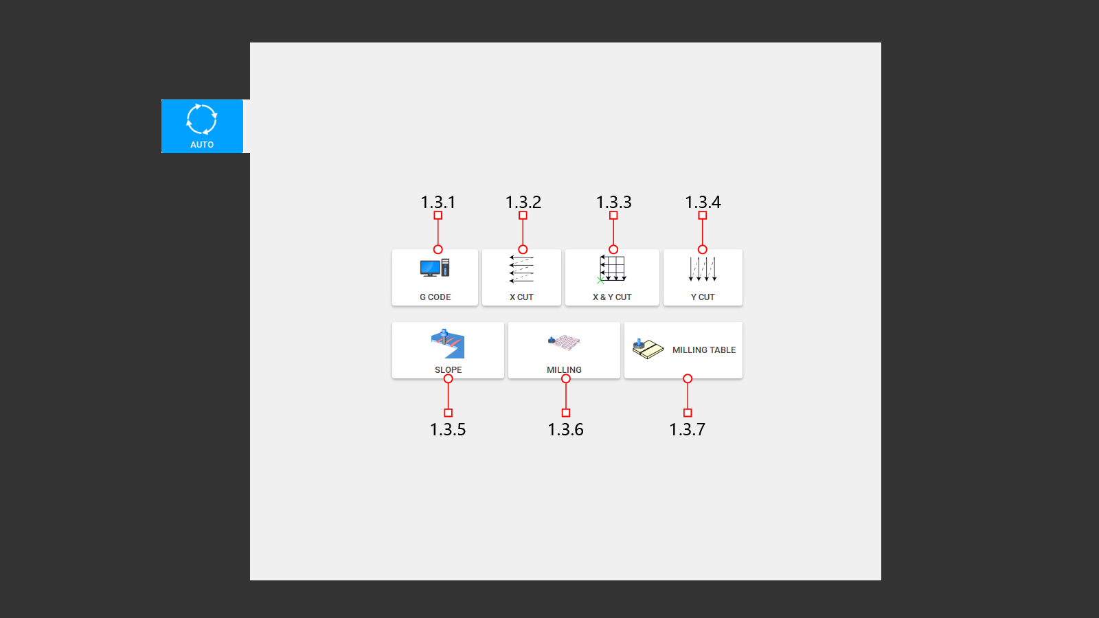
This tab displays the main built-in tabs for writing automatic control programs. Programs can be downloaded from a previously written program or you can create a control program directly on the machine using your own data for cutting and milling.
¶ 1.3.1 G Code
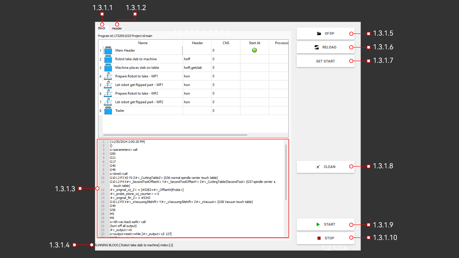
This tab opens a window to download the program written for the machine in the Pegasus software. The window contains the main controls and shows the progress of the downloaded program when it is being executed.
¶ 1.3.1.1 Block
This is a block of machine actions according to a written program divided by the number of control commands required for the machine.
¶ 1.3.1.2 Header
¶ 1.3.1.3 Code
This window displays programs in the form of G codes. Here you can view the actions of the machine when executing the program. The window displays data that can be useful for the operator and the machine operation before starting the program.
¶ 1.3.1.4 Info
The line displays the command that the machine is currently executing.
¶ 1.3.1.5 Open
The button opens a folder with written programs for the machine. In this folder, the operator must select the necessary program to perform the work in automatic mode.
¶ 1.3.1.6 Reload
With this button, the operator can resume the previously selected program. This is necessary if any changes have been made to the program and it was saved with the same name. The machine will simply update the data for this program.
¶ 1.3.1.7 Set Start
With this button, the operator can select any line in the Block window and the machine will execute programs from this location. To do this, you must first select the desired program line and press Set start. A green marker should appear on this line, which means that the operator has chosen to start the program from the specified location.
¶ 1.3.1.8 Clean
The button is necessary to clear the machine's memory of the downloaded program. Deletes it from the display block, but does not delete it from the folder with written programs.
¶ 1.3.1.9 Start
A button to start the execution of the downloaded program. The program will start running from the very beginning or from the location selected by the operator. The machine will execute all commands that are written according to the program, measuring the diameter or length of the tool, checking the name of the tools. It will move to the required location, turn on the spindle and cooling, and start working.
¶ 1.3.1.10 Stop
A button to stop the program at the current time. The machine will stop in any position and at any time during the execution of the program. All devices used for operation will stop working. Stopping the movement along the axes, turning off the spindle and cooling the tool. On the Block tab, the operator will see the stop step. It will be marked with a green marker.
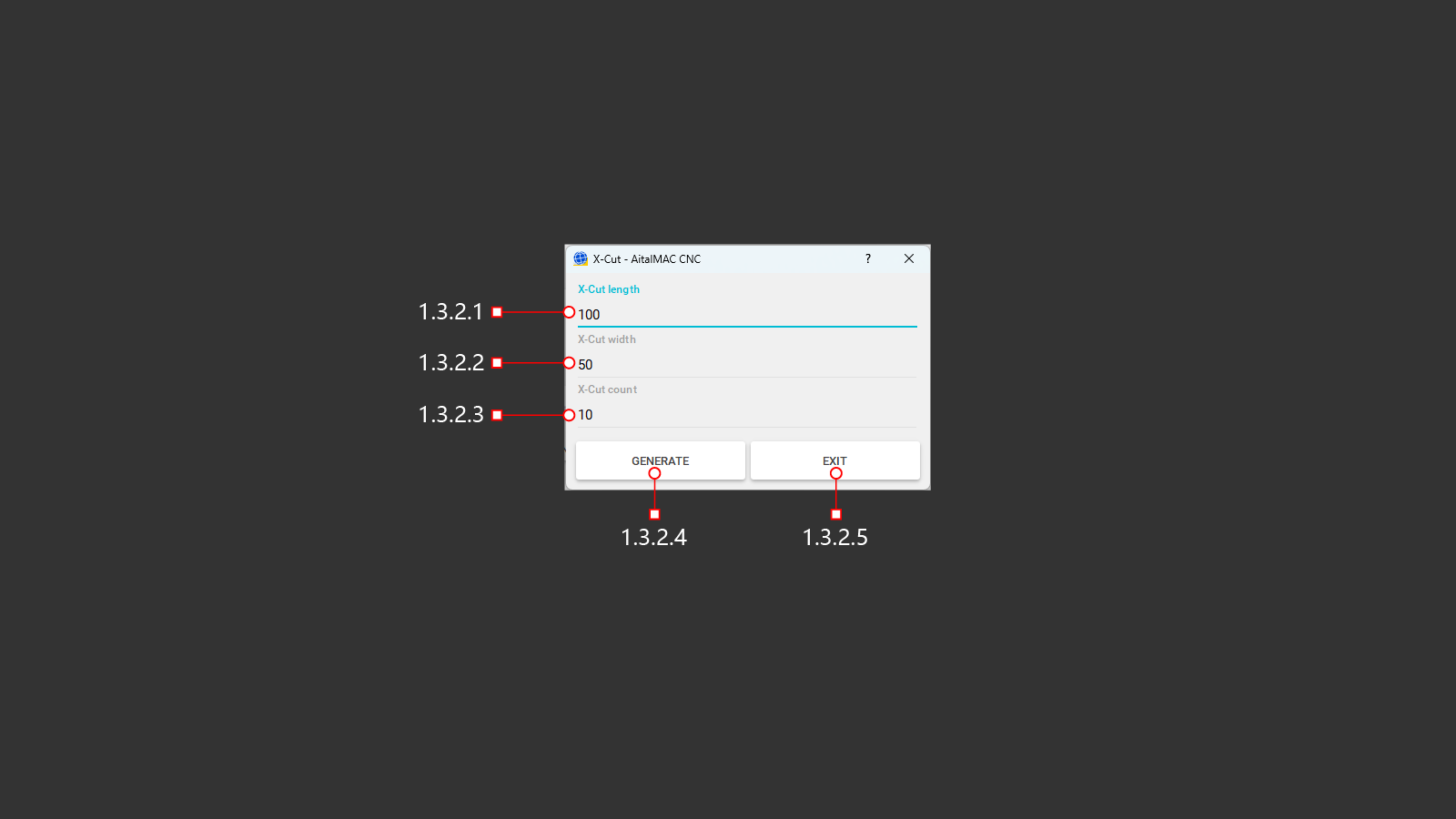
¶ 1.3.2 X Cut
A button to open the menu to create a program for automatic cutting of the material. The operator has the option to use the built-in compiler to create simple programs. For linear cuts along the X-axis. The icon shows the program execution diagram, from right to left and up. This function is used with a cutting disc. It is convenient for cutting the material into identical strips.
¶ 1.3.2.1 X-Cut Length
In the line, you must specify the length of the cut to be performed. The starting point of the cut will occur from the actual position of the cutting tool of the machine above the material.
¶ 1.3.2.2 X-Cut Width
The line must specify the width of the required cut-out part. After executing the length-cutting command, the machine will rise to a safe height and move to the starting point along the X-axis and offset along the Y-axis with the distance indicated in the row.
¶ 1.3.2.3 X-Cut Count
The number of parts that need to be made must be specified in the line. This will be the number of repetitions of the first two commands to execute the program.
¶ 1.3.2.4 Generate
A button for creating a control program to perform tasks based on previously entered cutting parameters. After clicking, the operator will be able to see the program G-code and visualization on the screen in the upper right corner.
¶ 1.3.2.5 Exit
Exit the menu without creating and saving a program for cutting the material. Return to the previous menu.
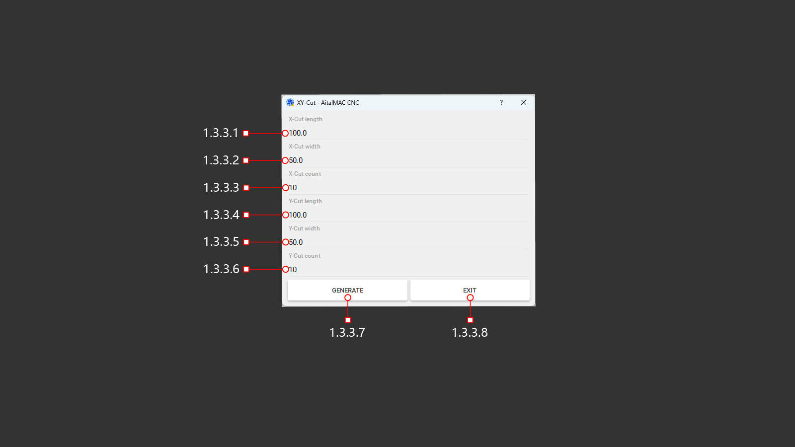
¶ 1.3.3 X&Y Cut
A button to open the menu to create a program for automatic cutting of the material. The operator has the option to use the built-in compiler to create simple programs. For linear cuts along the X and Y axes, the program execution diagram is shown on the icon, from right to left and up. This function is used with a cutting disc. A cross laser is used as the starting point for creating the program. To cut along the Y axis, the machine head will be rotated 90° along the C axis. It is convenient for cutting the material into identical squares or rectangles.
¶ 1.3.3.1 X-Cut Length
In the line, you must specify the length of the cut to be performed. The starting point of the cut will be the position of the laser cross.
¶ 1.3.3.2 X-Cut Width
The line must specify the width of the required cut-out part. After executing the length-cutting command, the machine will rise to a safe height and move to the starting point along the X-axis and offset along the Y-axis with the distance indicated in the row.
¶ 1.3.3.3 X-Cut Count
The number of parts that need to be made must be specified in the line. This will be the number of repetitions of the first two commands to execute the program.
¶ 1.3.3.4 Y-Cut Length
In the line, you must specify the length of the cut to be performed. The starting point of the cut will be the position of the laser cross.
¶ 1.3.3.5 Y-Cut Width
The line must specify the width of the required cut-out part. After executing the length-cutting command, the machine will rise to a safe height and move to the starting point along the X-axis and offset along the Y-axis with the distance indicated in the row.
¶ 1.3.3.6 Y-Cut Count
The number of parts that need to be made must be specified in the line. This will be the number of repetitions of the first two commands to execute the program.
¶ 1.3.3.7 Generate
A button for creating a control program to perform tasks based on previously entered cutting parameters. After clicking, the operator will be able to see the program G-code and visualization on the screen in the upper right corner.
¶ 1.3.3.8 Exit
Exit the menu without creating and saving a program for cutting the material. Return to the previous menu.
¶ 1.3.4 Y Cut

A button to open the menu to create a program for automatic cutting of the material. The operator has the option to use the built-in compiler to create simple programs. For linear cuts along the Y-axis. To cut along the Y axis, the machine head will be rotated 90° along the C axis. The icon shows the program execution diagram, from right to left and up. This function is used with a cutting disc.
¶ 1.3.4.1 Y-Cut Length
In the line, you must specify the length of the cut to be performed. The starting point of the cut will occur from the actual position of the cutting tool of the machine above the material.
¶ 1.3.4.2 Y-Cut Width
The line must specify the width of the required cut-out part. After executing the length-cutting command, the machine will rise to a safe height and move to the starting point along the X-axis and offset along the Y-axis with the distance indicated in the row.
¶ 1.3.4.3 Y-Cut Count
The number of parts that need to be made must be specified in the line. This will be the number of repetitions of the first two commands to execute the program.
¶ 1.3.4.4 Generate
A button for creating a control program to perform tasks based on previously entered cutting parameters. After clicking, the operator will be able to see the program G-code and visualization on the screen in the upper right corner.
¶ 1.3.4.5 Exit
Exit the menu without creating and saving a program for cutting the material. Return to the previous menu.
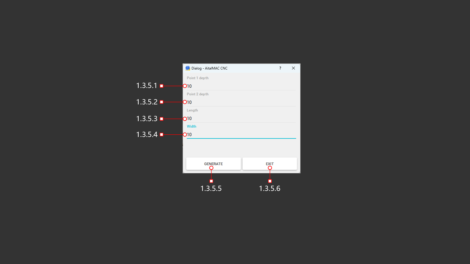
¶ 1.3.5 Slope
The button to open the menu for creating a slope on the surface of the material using the milling function. The starting point for creating the program will be the actual position of the machine above the material. Along the B axis, the machine should be moved by 90° and the milling tool is positioned perpendicular to the material above the starting point of the milling.
¶ 1.3.5.1 Point 1 Depth
Specify the initial milling depth. Starting from this point, the machine will gradually advance with a uniform deepening to the specified value at Point 2.
¶ 1.3.5.2 Point 2 Depth
Specify the final milling depth.
When this depth is reached, the machine will move on to the next command, if possible, or stop and move to a safe position.
¶ 1.3.5.3 Length
Specify the length for the slope milling. At this length, the machine will start working evenly from the initial depth at Point 1 and perform a deepening to the specified parameter of Point 2.
¶ 1.3.5.4 Width
Specify the width of the required slope milling surface. The width must not be less than the diameter of the installed milling tool, otherwise the work may not be done correctly.
¶ 1.3.5.5 Generate
A button for creating a control program to perform tasks based on previously entered cutting parameters. After clicking, the operator will be able to see the program G-code and visualization on the screen in the upper right corner.
¶ 1.3.5.6 Exit
Exit the menu without creating and saving a program for cutting the material. Return to the previous menu.
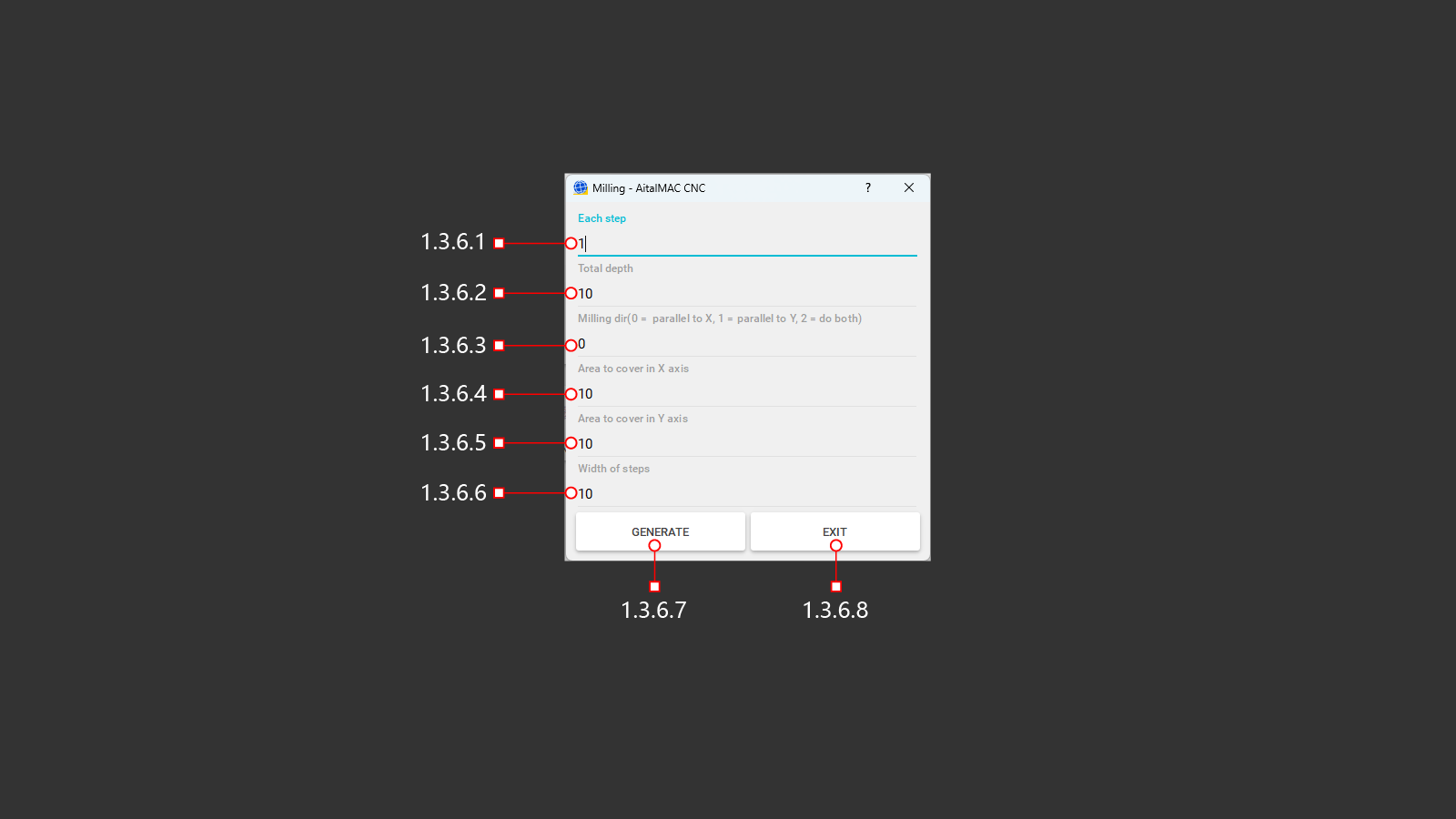
¶ 1.3.6 Milling
A button to open the milling menu of the material without a slope, in a strictly horizontal position. It is used to reduce the thickness of the material, on a certain area or on the entire material. The starting point for creating the program will be the actual position of the machine above the material. In the C-axis, the machine must be moved 90° and the milling tool positioned perpendicular to the material above the milling start point.
¶ 1.3.6.1 Each Step
The amount of deepening of the milling tool into the material in one step. Depending on the final depth, the processing will be divided into layers.
¶ 1.3.6.2 Total Depth
The value of the milling depth that the machine must reach by the end of the work. Based on the size of the deepening step, the required number of passes will be made to achieve full depth.
¶ 1.3.6.3 Milling Direction
Selection of the milling processing method selection of the required direction of movement and displacement. (0) - milling in the horizontal direction along the X-axis, making parallel passes with the specified offset. (1) - milling in the vertical direction along the Y-axis, making parallel passes with the specified offset. (2) - combined milling in the horizontal and vertical directions along the X and Y axes, performing parallel passes with the specified offset.
¶ 1.3.6.4 Area To Cover In X Axis
Specify the distance to be milled along the X-axis. The distance will be calculated relative to the center of the tool, not its diameter. These adjustments must be taken into account if it is necessary to perform milling in a limited space of the material.
¶ 1.3.6.5 Area To Cover In Y Axis
Specify the distance to be milled along the Y-axis. The distance will be calculated relative to the center of the tool, not its diameter. These adjustments must be taken into account if it is necessary to perform milling in a limited space of the material.
¶ 1.3.6.6 Width Of Steps
Specify the distance for the milling step. This is the offset for the next step, depending on the chosen milling method, it will be performed on the X or Y axis. The distance will be calculated relative to the center of the tool, not its diameter. These adjustments must be taken into account if it is necessary to perform milling operations in a limited material space.
¶ 1.3.6.7 Generate
A button for creating a control program to perform tasks based on previously entered milling parameters. After clicking, the operator will be able to see the program code and visualization on the screen in the upper right corner.
¶ 1.3.6.8 Exit
Exit the menu without creating and saving a program for cutting the material. Return to the previous menu.
¶ 1.3.7 Milling Table
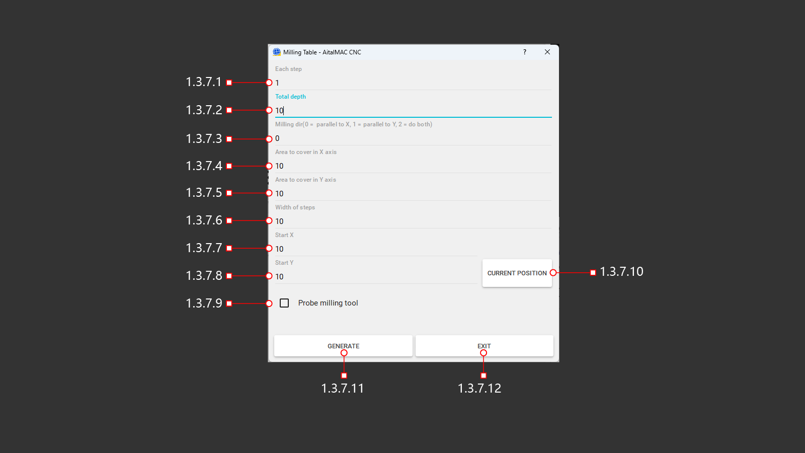
A button to open a special menu for milling the workbench in a strictly horizontal position to obtain the ideal level. It is used to reduce the thickness of the material, on a certain area or on the entire material. The starting point for creating the program will be the actual position of the machine above the material. In the C-axis, the machine must be moved 90° and the milling tool positioned perpendicular to the material above the milling start point.
¶ 1.3.7.1 Each Step
The amount of deepening of the milling tool into the material in one step. Depending on the final depth, the processing will be divided into layers.
¶ 1.3.7.2 Total Depth
The value of the milling depth that the machine must reach by the end of the work. Based on the size of the deepening step, the required number of passes will be made to achieve full depth.
¶ 1.3.7.3 Milling Direction
Selection of the milling processing method selection of the required direction of movement and displacement. (0) - milling in the horizontal direction along the X-axis, making parallel passes with the specified offset. (1) - milling in the vertical direction along the Y-axis, making parallel passes with the specified offset. (2) - combined milling in the horizontal and vertical directions along the X and Y axes, performing parallel passes with the specified offset.
¶ 1.3.7.4 Area To Cover In X Axis
Specify the distance to be milled along the X-axis. The distance will be calculated relative to the center of the tool, not its diameter. These adjustments must be taken into account if it is necessary to perform milling in a limited space of the material.
¶ 1.3.7.5 Area To Cover In Y Axis
Specify the distance to be milled along the Y-axis. The distance will be calculated relative to the center of the tool, not its diameter. These adjustments must be taken into account if it is necessary to perform milling in a limited space of the material.
¶ 1.3.7.6 Width Of Steps
Specify the distance for the milling step. This is the offset for the next step, depending on the chosen milling method, it will be performed on the X or Y axis. The distance will be calculated relative to the center of the tool, not its diameter. These adjustments must be taken into account if it is necessary to perform milling operations in a limited material space.
¶ 1.3.7.7 Start X
A place to record the required X-axis position in the program parameters to start milling work. It is determined by the operator independently, determines the coordinates in advance in the upper-left menu 1.10.
¶ 1.3.7.8 Start Y
A place to record the required Y-axis position in the program parameters to start milling work. It is determined by the operator independently, determines the coordinates in advance in the upper-left menu 1.10.
¶ 1.3.7.9 Probe Milling Tool
Activation of the function of checking the length of the installed milling cutter. After checking, the actual length of the milling cutter will be recorded in the tool parameters and the machine will execute commands with the necessary corrections. The depth of immersion in the worktable, the beginning of milling according to the thickness of the material. This will help to avoid collisions and incorrect milling of the material, as well as collisions with the processed material.
¶ 1.3.7.10 Current Position
A button for recording X- and Y-axis positions in the program parameters to start milling work. The current position of the machine above the material will be recorded in the program parameters, all previous X and Y coordinates will be overwritten. If the processing coordinates are selected by the operator in advance, then you do not need to use this button.
¶ 1.3.7.11 Generate
A button for creating a control program to perform tasks based on previously entered milling parameters. After clicking, the operator will be able to see the program code and visualization on the screen in the upper right corner.
¶ 1.3.7.12 Exit
Exit the menu without creating and saving a program for cutting the material. Return to the previous menu.
¶ 1.4 MDI
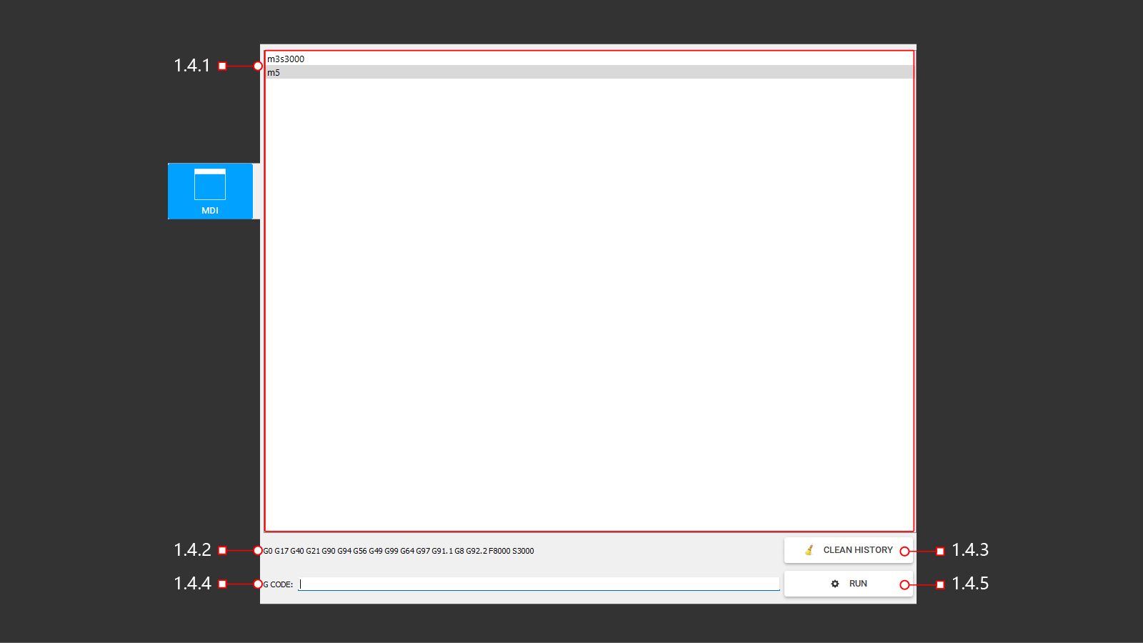
A mode that allows the operator to enter and execute G-code blocks on the control panel. In manual data entry mode, the code is entered one block at a time, and each block is removed from the machine immediately after execution.
¶ 1.4.1 List
Window to view the last command and previously used ones
¶ 1.4.2 Info
Possibly used and examples of G codes
¶ 1.4.3 Clean
Cleaning info window
¶ 1.4.4 G Code
Line for entering g command code
¶ 1.4.5 Run
Run the entered G code command
¶ 1.5 I/O
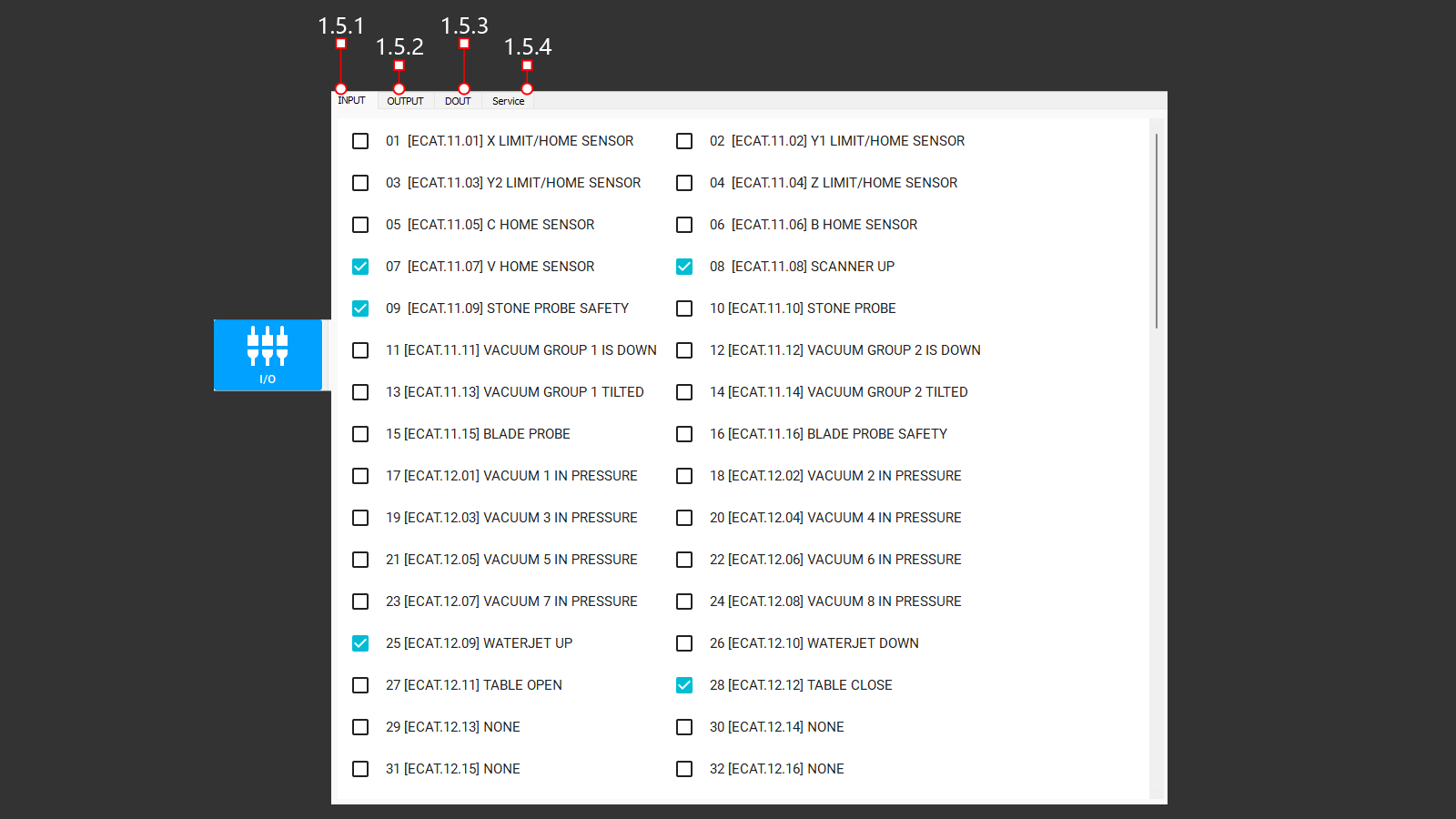
A tab that displays the input control signals from the machine control units. Responsible for safety, the position of the axes of the machine in relation to the limits, buttons and control joysticks, operating and deactivated modules for machine operation. The absence of a signal may be an indicator of an equipment malfunction, and is also necessary for checking and configuring
¶ 1.5.1 Input (1-32)
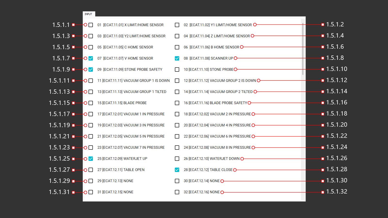
¶ 1.5.1.1 01 [ECAT.11.01] X Limit/Home Sensor
Input signal from the sensor along the X axis.
¶ 1.5.1.2 02 [ECAT.11.02] Y1 Limit/Home Sensor
Input signal from the sensor along the Y1 axis.
¶ 1.5.1.3 03 [ECAT.11.03] Y2 Limit/Home Sensor
Input signal from the sensor along the Y2 axis.
¶ 1.5.1.4 04 [ECAT.11.04] Z Limit/Home Sensor
Input signal from the sensor along the Z axis.
¶ 1.5.1.5 05 [ECAT.11.05] C Home Sensor
Input signal from the sensor along the C axis.
¶ 1.5.1.6 06 [ECAT.11.06] B Home Sensor
Input signal from the sensor along the B axis.
¶ 1.5.1.7 07 [ECAT.11.07] V Home Sensor
Input signal from the sensor along the V axis.
¶ 1.5.1.8 08 [ECAT.11.08] Scanner Up
Input signal from the sensor on the pneumatic cylinder to determine the position at the top.
¶ 1.5.1.9 09 [ECAT.11.09] Stone Probe Safety
Input signal from the sensor on the pneumatic cylinder to determine the position at the top.
¶ 1.5.1.10 10 [ECAT.11.10] Stone Probe
Input signal from the sensor on the pneumatic cylinder to determine the position at the bottom.
¶ 1.5.1.11 11 [ECAT.11.11] Vacuum Group 1 is Down
Input signal from the sensor on the pneumatic cylinder to determine the position at the bottom.
¶ 1.5.1.12 12 [ECAT.11.12] Vacuum Group 2 is Down
Input signal from the sensor on the pneumatic cylinder to determine the position at the bottom.
¶ 1.5.1.13 13 [ECAT.11.13] Vacuum Group 1 Tilted
Input signal from the sensor on the pneumatic cylinder to determine the position at the bottom.
¶ 1.5.1.14 14 [ECAT.11.14] Vacuum Group 2 Tilted
Input signal from the sensor on the pneumatic cylinder to determine the position at the bottom.
¶ 1.5.1.15 15 [ECAT.11.15] Blade Probe
The output signal from the probe is for measuring the diameter of the blade. The first position of touching the probe with the blade.
¶ 1.5.1.16 16 [ECAT.11.16] Blade Probe Safety
The output signal from the sensor is designed to measure the diameter of the blade. The second safety position of the sensor is with the blade.
¶ 1.5.1.17 17 [ECAT.12.01] Vacuum 1 in Pressure
Input signal from the sensor on the vacuum generator (1), switching on and off.
¶ 1.5.1.18 18 [ECAT.12.02] Vacuum 2 in Pressure
Input signal from the sensor on the vacuum generator (2), switching on and off.
¶ 1.5.1.19 19 [ECAT.12.03] Vacuum 3 in Pressure
Input signal from the sensor on the vacuum generator (3), switching on and off.
¶ 1.5.1.20 20 [ECAT.12.04] Vacuum 4 in Pressure
Input signal from the sensor on the vacuum generator (4), switching on and off.
¶ 1.5.1.21 21 [ECAT.12.05] Vacuum 5 in Pressure
Input signal from the sensor on the vacuum generator (5), switching on and off.
¶ 1.5.1.22 22 [ECAT.12.06] Vacuum 6 in Pressure
Input signal from the sensor on the vacuum generator (6), switching on and off.
¶ 1.5.1.23 23 [ECAT.12.07] Vacuum 7 in Pressure
Input signal from the sensor on the vacuum generator (7), switching on and off.
¶ 1.5.1.24 24 [ECAT.12.08] Vacuum 8 in Pressure
Input signal from the sensor on the vacuum generator (8), switching on and off.
¶ 1.5.1.25 25 [ECAT.12.09] Waterjet Up
Input signal from the sensor on the air cylinder to determine the position at the top.
¶ 1.5.1.26 26 [ECAT.12.10] Waterjet Down
Input signal from the sensor on the air cylinder to determine the position at the bottom.
¶ 1.5.1.27 27 [ECAT.12.11] Table Open
Input signal from the sensor on the hydraulic cylinder to determine the position of the open table.
¶ 1.5.1.28 28 [ECAT.12.12] Table Close
Input signal from the sensor on the hydraulic cylinder to determine the down position.
¶ 1.5.1.29 29 [ECAT.12.13] None
The input signal on the control card is not assigned
¶ 1.5.1.30 30 [ECAT.12.14] None
The input signal on the control card is not assigned
¶ 1.5.1.31 31 [ECAT.12.15] None
The input signal on the control card is not assigned
¶ 1.5.1.32 32 [ECAT.12.16] None
The input signal on the control card is not assigned
¶ 1.5.1 Input (33-64)
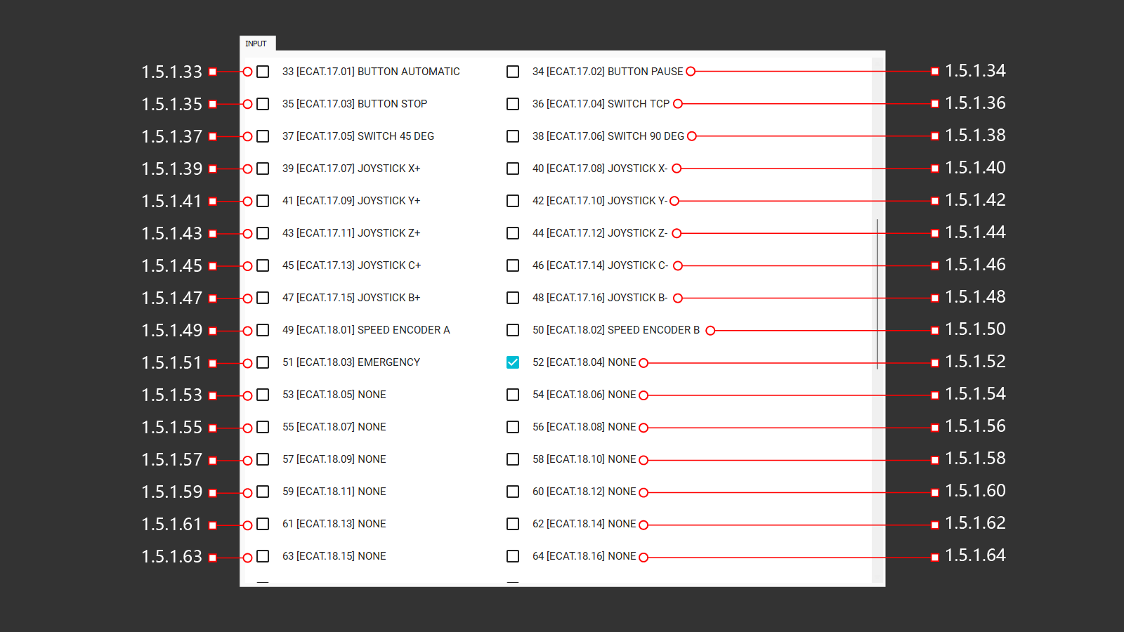
¶ 1.5.1.33 33 [ECAT.17.01] Button Automatic
Feedback from the start automatic operation button.
¶ 1.5.1.34 34 [ECAT.17.02] Button Pause
Feedback from the pause button of automatic operation.
¶ 1.5.1.35 35 [ECAT.17.03] Button Stop
Feedback from the stop button of automatic operation.
¶ 1.5.1.36 36 [ECAT.17.04] Switch TCP
Feedback signal for switching on the switch to activate axis interpolation
¶ 1.5.1.37 37 [ECAT.17.05] Switch 45 Deg
Feedback is a signal to turn on the switch to activate the rotation of the head by 45° along the B axis
¶ 1.5.1.38 38 [ECAT.17.06] Switch 90 Deg
Feedback is a signal to turn on the switch to activate the rotation of the head by 90° along the B axis
¶ 1.5.1.39 39 [ECAT.17.07] Joystick X+
Feedback is a signal to turn on the movement of the machine in the positive direction along the X-axis using the joystick on the control panel.
¶ 1.5.1.40 40 [ECAT.17.08] Joystick X-
Feedback is a signal to turn on the movement of the machine in the negative direction along the X-axis using the joystick on the control panel.
¶ 1.5.1.41 41 [ECAT.17.09] Joystick Y+
Feedback is a signal to turn on the movement of the machine in the positive direction along the Y-axis using the joystick on the control panel.
¶ 1.5.1.42 42 [ECAT.17.10] Joystick Y-
Feedback is a signal to turn on the movement of the machine in the negative direction along the Y-axis using the joystick on the control panel.
¶ 1.5.1.43 43 [ECAT.17.11] Joystick Z+
Feedback is a signal to turn on the movement of the machine in the positive direction along the Z-axis using the joystick on the control panel.
¶ 1.5.1.44 44 [ECAT.17.12] Joystick Z-
Feedback is a signal to turn on the movement of the machine in the negative direction along the Z-axis using the joystick on the control panel.
¶ 1.5.1.45 45 [ECAT.17.13] Joystick C+
Feedback is a signal to turn on the movement of the machine in the positive direction along the C-axis using the joystick on the control panel.
¶ 1.5.1.46 46 [ECAT.17.14] Joystick C-
Feedback is a signal to turn on the movement of the machine in the negative direction along the C-axis using the joystick on the control panel.
¶ 1.5.1.47 47 [ECAT.17.15] Joystick B+
Feedback is a signal to turn on the movement of the machine in the positive direction along the B-axis using the joystick on the control panel.
¶ 1.5.1.48 48 [ECAT.17.16] Joystick B-
Feedback is a signal to turn on the movement of the machine in the negative direction along the B-axis using the joystick on the control panel.
¶ 1.5.1.49 49 [ECAT.18.01] Speed Encoder A
¶ 1.5.1.50 50 [ECAT.18.02] Speed Encoder B
¶ 1.5.1.51 51 [ECAT.18.03] Emergency
Feedback from the emergency stop button. The signal indicates that the button is on.
¶ 1.5.1.52 52 [ECAT.18.04] None
The input signal on the control card is not assigned
¶ 1.5.1.53 53 [ECAT.18.05] None
The input signal on the control card is not assigned
¶ 1.5.1.54 54 [ECAT.18.06] None
The input signal on the control card is not assigned
¶ 1.5.1.55 55 [ECAT.18.07] None
The input signal on the control card is not assigned
¶ 1.5.1.56 56 [ECAT.18.08] None
The input signal on the control card is not assigned
¶ 1.5.1.57 57 [ECAT.18.09] None
The input signal on the control card is not assigned
¶ 1.5.1.58 58 [ECAT.18.10] None
The input signal on the control card is not assigned
¶ 1.5.1.59 59 [ECAT.18.11] None
The input signal on the control card is not assigned
¶ 1.5.1.60 60 [ECAT.18.12] None
The input signal on the control card is not assigned
¶ 1.5.1.61 61 [ECAT.18.13] None
The input signal on the control card is not assigned
¶ 1.5.1.62 62 [ECAT.18.14] None
The input signal on the control card is not assigned
¶ 1.5.1.63 63 [ECAT.18.15] None
The input signal on the control card is not assigned
¶ 1.5.1.64 64 [ECAT.18.16] None
The input signal on the control card is not assigned
¶ 1.5.1 Input (65-96)
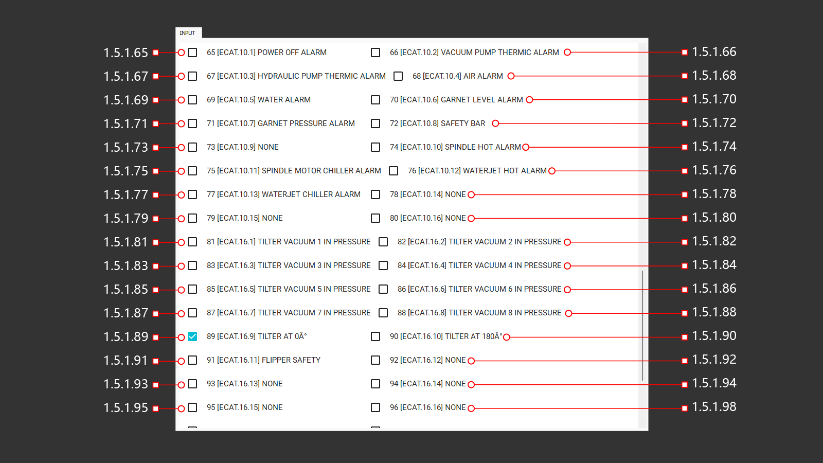
¶ 1.5.1.65 65 [ECAT.10.1] Power Off Alarm
The input signal indicating a power failure due to an error is incompatible with the machine's ability to continue operation.
¶ 1.5.1.66 66 [ECAT.10.2] Vacuum Pump Thermic Alarm
The initial input for the thermal protection mechanism of the vacuum motor.
¶ 1.5.1.67 67 [ECAT.10.3] Hydraulic Pump Thermic Alarm
The initial input for the thermal protection mechanism of the hydraulic motor.
¶ 1.5.1.68 68 [ECAT.10.4] Air Alarm
The input signal is obtained from the readings of the air pressure sensor located at the entrance of the machine. If the air pressure falls below a certain threshold, a trigger event is activated.
¶ 1.5.1.69 69 [ECAT.10.5] Water Alarm
The input signal is obtained from the readings of the water pressure sensor located at the entrance of the machine. If the water pressure falls below a certain threshold, a trigger event is activated.
¶ 1.5.1.70 70 [ECAT.10.6] Garnet Level Alarm
The output signal is generated based on the readings of a capacitive sensor located in the garnet abrasive tank. If the abrasive level falls below a certain threshold value, a trigger event is activated.
¶ 1.5.1.71 71 [ECAT.10.7] Garnet Pressure Alarm
The output signal is generated based on the readings of the pressure sensor in the garnet abrasive tank. If the pressure in the tank drops below a certain level, automatic abrasive supply becomes impossible and an alert is triggered.
¶ 1.5.1.72 72 [ECAT.10.8] Safety Bar
The output signal is generated based on the readings from the safety sensor during machine operation. If these readings indicate a potential emergency, the signal stops the machine operation to prevent any further accidents in the machine area.
¶ 1.5.1.73 73 [ECAT.10.9] None
The input signal on the control card is not assigned
¶ 1.5.1.74 74 [ECAT.10.10] Spindle Hot Alarm
The input signal is generated based on the readings of the spindle's overheating sensor during the thermal test. If a signal is detected, the spindle will stop to prevent serious damage.
¶ 1.5.1.75 75 [ECAT.10.11] Spindle Motor Chiller Alarm
The output signal is generated based on readings from the Chiller control panel. If a signal is received, the power supply is stopped to prevent serious damage. It is necessary to fix the problem on the Chiller.
¶ 1.5.1.76 76 [ECAT.10.12] Waterjet Hot Alarm
The input signal is generated based on the readings (thermal test) of the motor overheating sensor. If a signal is received, the motor power supply stops to prevent serious damage.
¶ 1.5.1.77 77 [ECAT.10.13] Waterjet Chiller Alarm
The output signal is generated based on readings from the Chiller control panel. If a signal is received, the power supply is stopped to prevent serious damage. It is necessary to fix the problem on the Chiller.
¶ 1.5.1.78 78 [ECAT.10.14] None
The input signal on the control card is not assigned
¶ 1.5.1.79 79 [ECAT.10.15] None
The input signal on the control card is not assigned
¶ 1.5.1.80 80 [ECAT.10.16] None
The input signal on the control card is not assigned
¶ 1.5.1.81 81 [ECAT.16.1] Tilter Vacuum 1 in Pressure
The input signal from the vacuum monitoring sensor on the suction cups indicates whether there is a vacuum present or not. If the vacuum is created on a suction cup, it is possible to lift and flipping the material on the workbench. If not, a signal will appear to check the suction cup with the number where there is no vacuum.
¶ 1.5.1.82 82 [ECAT.16.2] Tilter Vacuum 2 in Pressure
The input signal from the vacuum monitoring sensor on the suction cups indicates whether there is a vacuum present or not. If the vacuum is created on a suction cup, it is possible to lift and flipping the material on the workbench. If not, a signal will appear to check the suction cup with the number where there is no vacuum.
¶ 1.5.1.83 83 [ECAT.16.3] Tilter Vacuum 3 in Pressure
The input signal from the vacuum monitoring sensor on the suction cups indicates whether there is a vacuum present or not. If the vacuum is created on a suction cup, it is possible to lift and flippinf the material on the workbench. If not, a signal will appear to check the suction cup with the number where there is no vacuum.
¶ 1.5.1.84 84 [ECAT.16.4] Tilter Vacuum 4 in Pressure
The input signal from the vacuum monitoring sensor on the suction cups indicates whether there is a vacuum present or not. If the vacuum is created on a suction cup, it is possible to lift and flipping the material on the workbench. If not, a signal will appear to check the suction cup with the number where there is no vacuum.
¶ 1.5.1.85 85 [ECAT.16.5] Tilter Vacuum 5 in Pressure
The input signal from the vacuum monitoring sensor on the suction cups indicates whether there is a vacuum present or not. If the vacuum is created on a suction cup, it is possible to lift and flipping the material on the workbench. If not, a signal will appear to check the suction cup with the number where there is no vacuum.
¶ 1.5.1.86 86 [ECAT.16.6] Tilter Vacuum 6 in Pressure
The input signal from the vacuum monitoring sensor on the suction cups indicates whether there is a vacuum present or not. If the vacuum is created on a suction cup, it is possible to lift and flipping the material on the workbench. If not, a signal will appear to check the suction cup with the number where there is no vacuum.
¶ 1.5.1.87 87 [ECAT.16.7] Tilter Vacuum 7 in Pressure
The input signal from the vacuum monitoring sensor on the suction cups indicates whether there is a vacuum present or not. If the vacuum is created on a suction cup, it is possible to lift and flipping the material on the workbench. If not, a signal will appear to check the suction cup with the number where there is no vacuum.
¶ 1.5.1.88 88 [ECAT.16.8] Tilter Vacuum 8 in Pressure
The input signal from the vacuum monitoring sensor on the suction cups indicates whether there is a vacuum present or not. If the vacuum is created on a suction cup, it is possible to lift and flipping the material on the workbench. If not, a signal will appear to check the suction cup with the number where there is no vacuum.
¶ 1.5.1.89 89 [ECAT.16.9] Tilter At 0a°
The input signal comes from the position sensor of the additional vacuum suction cups. The suction cups are lifted and rotated to flip the material.
¶ 1.5.1.90 90 [ECAT.16.10] Tilter At 180a°
The input signal from the position sensor of the additional vacuum suction cups. The suction cups are lowered and the machine can perform work on flipping the material on the workbench.
¶ 1.5.1.91 91 [ECAT.16.11] Flipper Safety
The input signal is from the position sensor of the plate flip system with vacuum suction cups. The suction cups are lowered to a safe position and the machine can perform cutting and milling operations.
¶ 1.5.1.92 92 [ECAT.16.12] None
The input signal on the control card is not assigned
¶ 1.5.1.93 93 [ECAT.16.13] None
The input signal on the control card is not assigned
¶ 1.5.1.94 94 [ECAT.16.14] None
The input signal on the control card is not assigned
¶ 1.5.1.95 95 [ECAT.16.15] None
The input signal on the control card is not assigned
¶ 1.5.1.96 96 [ECAT.16.16] None
The input signal on the control card is not assigned
¶ 1.5.1 Input (97-108)
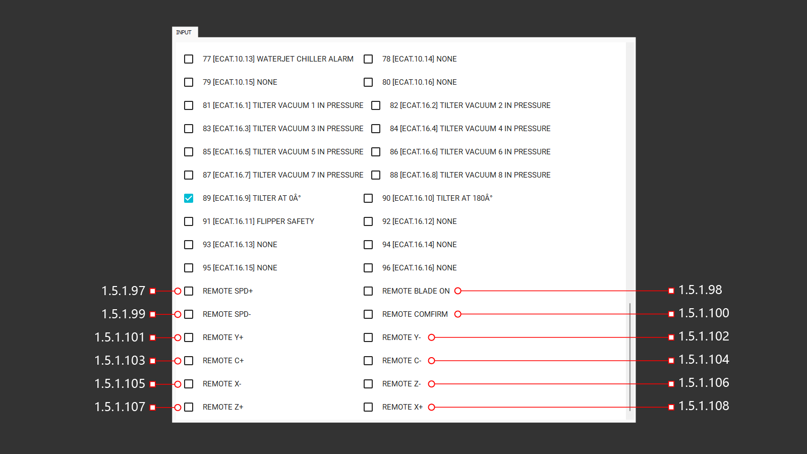
¶ 1.5.1.97 Remote Spd+
The input signal is a change in the speed of the spindle as a percentage of its initial speed.
¶ 1.5.1.98 Remote Blade On
Input signal for turning on the spindle from the remote control
¶ 1.5.1.99 Remote Spd-
The input signal is used to reduce the speed of the spindle as a percentage of its initial speed.
¶ 1.5.1.100 Remote Confirm
The input signal for connecting the remote control
¶ 1.5.1.101 Remote Y+
An input signal to enable the movement of the machine in a positive direction along the Y-axis using the remote control.
¶ 1.5.1.102 Remote Y-
An input signal to turn on the movement of the machine in the negative direction along the Y-axis using the remote control.
¶ 1.5.1.103 Remote C+
An input signal to enable the movement of the machine in a positive direction along the C-axis using the remote control.
¶ 1.5.1.104 Remote C-
An input signal to turn on the movement of the machine in the negative direction along the C-axis using the remote control.
¶ 1.5.1.105 Remote X-
An input signal to turn on the movement of the machine in the negative direction along the X-axis using the remote control.
¶ 1.5.1.106 Remote Z-
An input signal to turn on the movement of the machine in the negative direction along the Z-axis using the remote control.
¶ 1.5.1.107 Remote Z+
An input signal to enable the movement of the machine in a positive direction along the Z-axis using the remote control.
¶ 1.5.1.108 Remote X+
An input signal to enable the movement of the machine in a positive direction along the X-axis using the remote control.
¶ 1.5.2 Output (1-32)
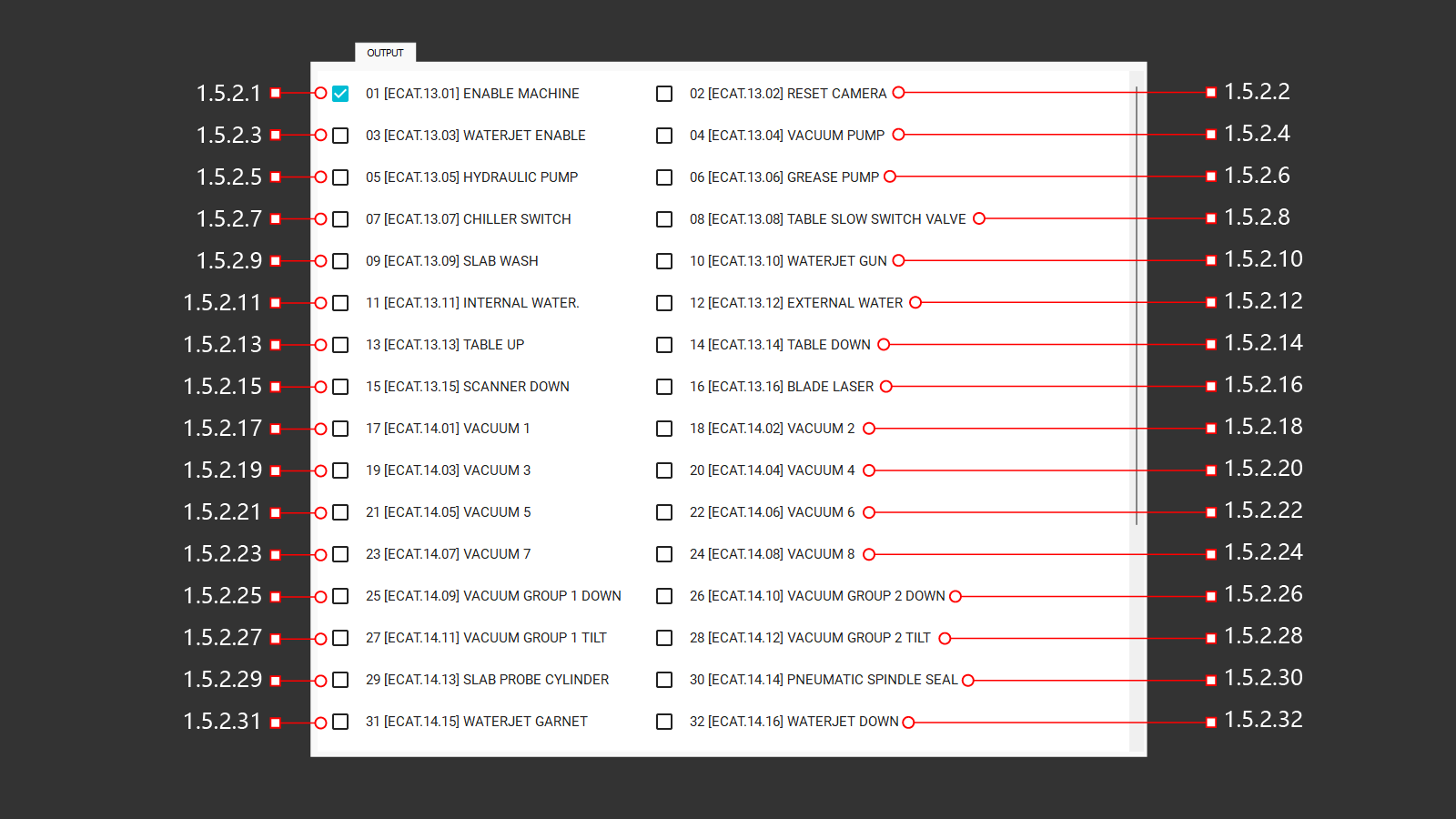
A tab with the output signals from the main modules and components of the machine. The operator can use this tab to check the operation of selected commands, see how the machine is performing, and, if necessary, make adjustments.Care must be taken when using the output signals, because the commands are forced and do not match the safe positions of the machine.
¶ 1.5.2.1 01 [ECAT.13.01] Enable Machine
Activates the machine. This signal also triggers when the machine is turned on from the operator menu.
¶ 1.5.2.2 02 [ECAT.13.02] Reset Camera
Resets (reboots) the camera used for taking images of material on the workbench. This is useful when the camera loses connection.
¶ 1.5.2.3 03 [ECAT.13.03] Waterjet Enable
Activates the water jet. This signal is also given when the machine is turned on from the operator's menu.
¶ 1.5.2.4 04 [ECAT.13.04] Vacuum Pump
Activates the vacuum pump, creating a vacuum in the system. This signal is necessary for testing all vacuum suction cups. Each suction cup can be tested individually by activating its respective output signal.
¶ 1.5.2.5 05 [ECAT.13.05] Hydraulic Pump
Activates the hydraulic station motor. This begins building oil pressure for lifting the workbench. Without this signal, the hydraulic distributor will keep the workbench in its initial position.
¶ 1.5.2.6 06 [ECAT.13.06] Grease Pump
Activates the automatic lubrication pump. The pump normally operates at set intervals and durations, but manual activation can verify lubrication flow after refilling the grease tank or during maintenance of lubrication lines.
¶ 1.5.2.7 07 [ECAT.13.07] Chiller Switch
Activating chiller shutdown
¶ 1.5.2.8 08 [ECAT.13.08] Table Slow Switch Valve
Активация дополнительного гидроклапана для замедления опускания механизма верстака (устанавливается опционально)
¶ 1.5.2.9 09 [ECAT.13.09] Slab Wash
Activates the material cleaning system. This opens the water supply valve for cleaning nozzles.
¶ 1.5.2.10 10 [ECAT.13.10] Waterjet Gun
Активация клапана открытия подачи воды на режущую головку.
¶ 1.5.2.11 11 [ECAT.13.11] Internal Water
Enables water flow through the spindle center for milling operations. Activating this signal opens the respective water and air supply valves.
¶ 1.5.2.12 12 [ECAT.13.12] External Water
Enables the external cooling system for tools, such as blades. This signal opens the valve to supply water through nozzles directed at the blade.
¶ 1.5.2.13 13 [ECAT.13.13] Table Up
Activates the solenoids of the hydraulic distributor to forcibly lift the workbench. This requires the hydraulic station to be active. Without it, the distributor will only switch the oil flow to the lift cylinder. The command bypasses safe position checks, requiring operator supervision.
¶ 1.5.2.14 14 [ECAT.13.14] Table Down
Activates the solenoids of the hydraulic distributor to forcibly lower the workbench. This requires the hydraulic station to be active. Without it, the distributor will only switch the oil flow to the cylinder for lowering. The command bypasses safe position checks, requiring operator supervision.
¶ 1.5.2.15 15 [ECAT.15.15] Scaner Down
Lowers the laser scanner module for material thickness measurement along the cutting path. The command ignores Z-axis safe position checks, so operators must ensure the head is positioned to avoid collisions.
¶ 1.5.2.16 16 [ECAT.13.16] Blade Laser
Enables the blade laser line for alignment checks. Pressing the button again turns off the laser.
¶ 1.5.2.17 17 [ECAT.14.01] Vacuum 1
Activates the vacuum for suction cup 1. This signal only works when the vacuum pump is active.
¶ 1.5.2.18 18 [ECAT.14.02] Vacuum 2
Activates the vacuum for suction cup 2. This signal only works when the vacuum pump is active.
¶ 1.5.2.19 19 [ECAT.14.03] Vacuum 3
Activates the vacuum for suction cup 3. This signal only works when the vacuum pump is active.
¶ 1.5.2.20 20 [ECAT.14.04] Vacuum 4
Activates the vacuum for suction cup 4. This signal only works when the vacuum pump is active.
¶ 1.5.2.21 21 [ECAT.14.05] Vacuum 5
Activates the vacuum for suction cup 5. This signal only works when the vacuum pump is active.
¶ 1.5.2.22 22 [ECAT.14.06] Vacuum 6
Activates the vacuum for suction cup 6. This signal only works when the vacuum pump is active.
¶ 1.5.2.23 23 [ECAT.14.07] Vacuum 7
Activates the vacuum for suction cup 7. This signal only works when the vacuum pump is active.
¶ 1.5.2.24 24 [ECAT.14.08] Vacuum 8
Activates the vacuum for suction cup 8. This signal only works when the vacuum pump is active.
¶ 1.5.2.25 25 [ECAT.14.09] Vacuum Group 1 Down
Activates the signal to lower vacuum modules in Group 1. Operators must ensure sufficient Z-axis clearance before initiating this action to avoid collisions.
¶ 1.5.2.26 26 [ECAT.14.10] Vacuum Group 2 Down
Activates the signal to lower vacuum modules in Group 2. Like Group 1, operators must verify adequate Z-axis clearance prior to operation.
¶ 1.5.2.27 27 [ECAT.14.11] Vacuum Group 1 Tilt
Tilts vacuum modules in Group 1 horizontally. Ensure Z-axis clearance is sufficient to prevent interference during operation.
¶ 1.5.2.28 28 [ECAT.14.12] Vacuum Group 2 Tilt
Tilts vacuum modules in Group 2 horizontally. Operators should confirm Z-axis clearance before activating this signal.
¶ 1.5.2.29 29 [ECAT.14.13] Slab Probe Cylinder
Lowers the probe for material thickness measurement. Activating the signal opens the air supply valve, and deactivating it retracts the probe.
¶ 1.5.2.30 30 [ECAT.14.14] Pneumatic Spindle Seal
Enables air supply through the spindle center for sealing. The operator can adjust pressure or check seal integrity.
¶ 1.5.2.31 31 [ECAT.14.15] Waterjet Garnet
Opens the valve to supply garnet for the waterjet cutting head. Operators should flush the tube after manual operation to prevent blockages.
¶ 1.5.2.32 32 [ECAT.14.16] Waterjet Down
Lowers the waterjet cutting head into position. Operators must ensure sufficient Z-axis clearance before activation.
¶ 1.5.2 Output (33-48)
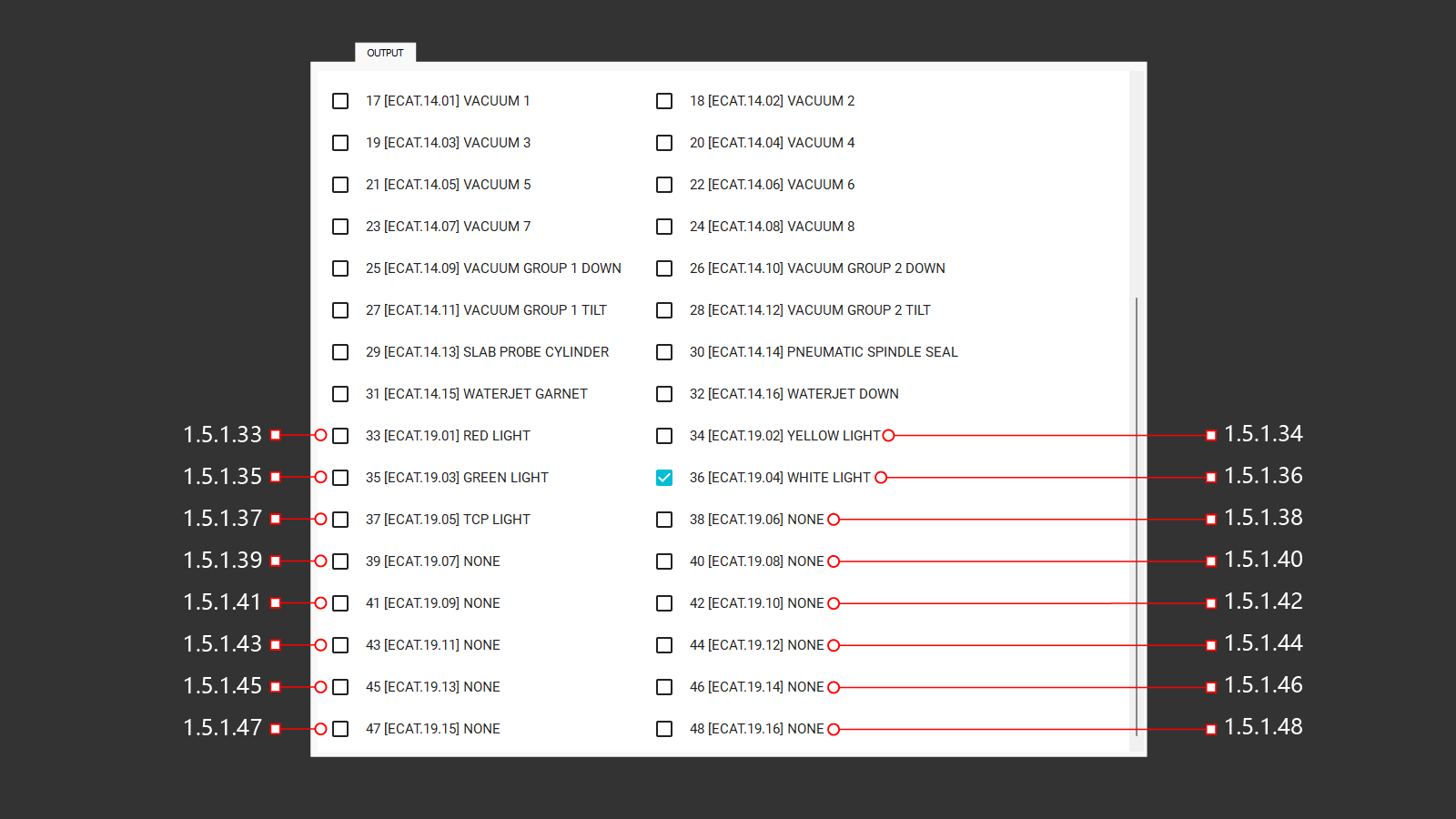
¶ 1.5.2.33 33 [ECAT.19.01] Red Light
Activates the red warning light on the control panel. The red light signals errors or alerts operators that the machine is ready for operation.
¶ 1.5.2.34 34 [ECAT.19.02] Yellow Light
Activates the yellow light on the control panel. The yellow light signals that the machine is in pause mode. However, this output forces the yellow light on regardless of the actual machine state and can be used to test the signal lamp.
¶ 1.5.2.35 35 [ECAT.19.03] Green Light
Activates the green light on the control panel. A green light warns the operator when the machine is working.
¶ 1.5.2.36 36 [ECAT.19.04] White Light
Activates the white light on the control panel. A white light warns the operator about making machine settings
¶ 1.5.2.37 37 [ECAT.19.05] TCP Light
Activates the green illumination of the switch. The green light indicates that interpolation is enabled.
¶ 1.5.2.38 38 [ECAT.19.06] None
The output signal on the control board is not set
¶ 1.5.2.39 39 [ECAT.19.07] None
The output signal on the control board is not set
¶ 1.5.2.40 40 [ECAT.19.08] None
The output signal on the control board is not set
¶ 1.5.2.41 41 [ECAT.19.09] None
The output signal on the control board is not set
¶ 1.5.2.42 42 [ECAT.19.10] None
The output signal on the control board is not set
¶ 1.5.2.43 43 [ECAT.19.11] None
The output signal on the control board is not set
¶ 1.5.2.44 44 [ECAT.19.12] None
The output signal on the control board is not set
¶ 1.5.2.45 45 [ECAT.19.13] None
The output signal on the control board is not set
¶ 1.5.2.46 46 [ECAT.19.14] None
The output signal on the control board is not set
¶ 1.5.2.47 47 [ECAT.19.15] None
The output signal on the control board is not set
¶ 1.5.2.48 48 [ECAT.19.16] None
The output signal on the control board is not set
¶ 1.5.3 Dout (1-16)
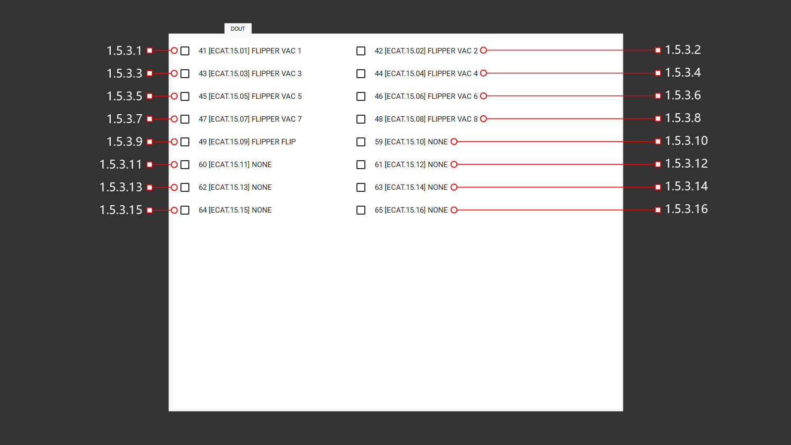
¶ 1.5.3.1 1 [ECAT.15.01] Flipper Vac 1
Activates the vacuum suction cup (1) on the tile flip module.
¶ 1.5.3.2 42 [ECAT.15.02] Flipper Vac 2
Activates the vacuum suction cup (2) on the tile flip module.
¶ 1.5.3.3 43 [ECAT.15.03] Flipper Vac 3
Activates the vacuum suction cup (3) on the tile flip module.
¶ 1.5.3.4 44 [ECAT.15.04] Flipper Vac 4
Activates the vacuum suction cup (4) on the tile flip module.
¶ 1.5.3.5 45 [ECAT.15.05] Flipper Vac 5
Activates the vacuum suction cup (5) on the tile flip module.
¶ 1.5.3.6 46 [ECAT.15.06] Flipper Vac 6
Activates the vacuum suction cup (6) on the tile flip module.
¶ 1.5.3.7 47 [ECAT.15.07] Flipper Vac 7
Activates the vacuum suction cup (7) on the tile flip module.
¶ 1.5.3.8 48 [ECAT.15.08] Flipper Vac 8
Activates the vacuum suction cup (8) on the tile flip module.
¶ 1.5.3.9 49 [ECAT.15.09] Flipper Flip
Activates a 180° rotation of the module. The command will execute without safety checks, so the operator must carefully monitor the module's position.
¶ 1.5.3.10 59 [ECAT.15.10] None
The output signal on the control board is not set
¶ 1.5.3.11 60 [ECAT.15.11] None
The output signal on the control board is not set
¶ 1.5.3.12 61 [ECAT.15.12] None
The output signal on the control board is not set
¶ 1.5.3.13 62 [ECAT.15.13] None
The output signal on the control board is not set
¶ 1.5.3.14 63 [ECAT.15.14] None
The output signal on the control board is not set
¶ 1.5.3.15 64 [ECAT.15.15] None
The output signal on the control board is not set
¶ 1.5.3.16 65 [ECAT.15.16] None
The output signal on the control board is not set
¶ 1.5.4 Service
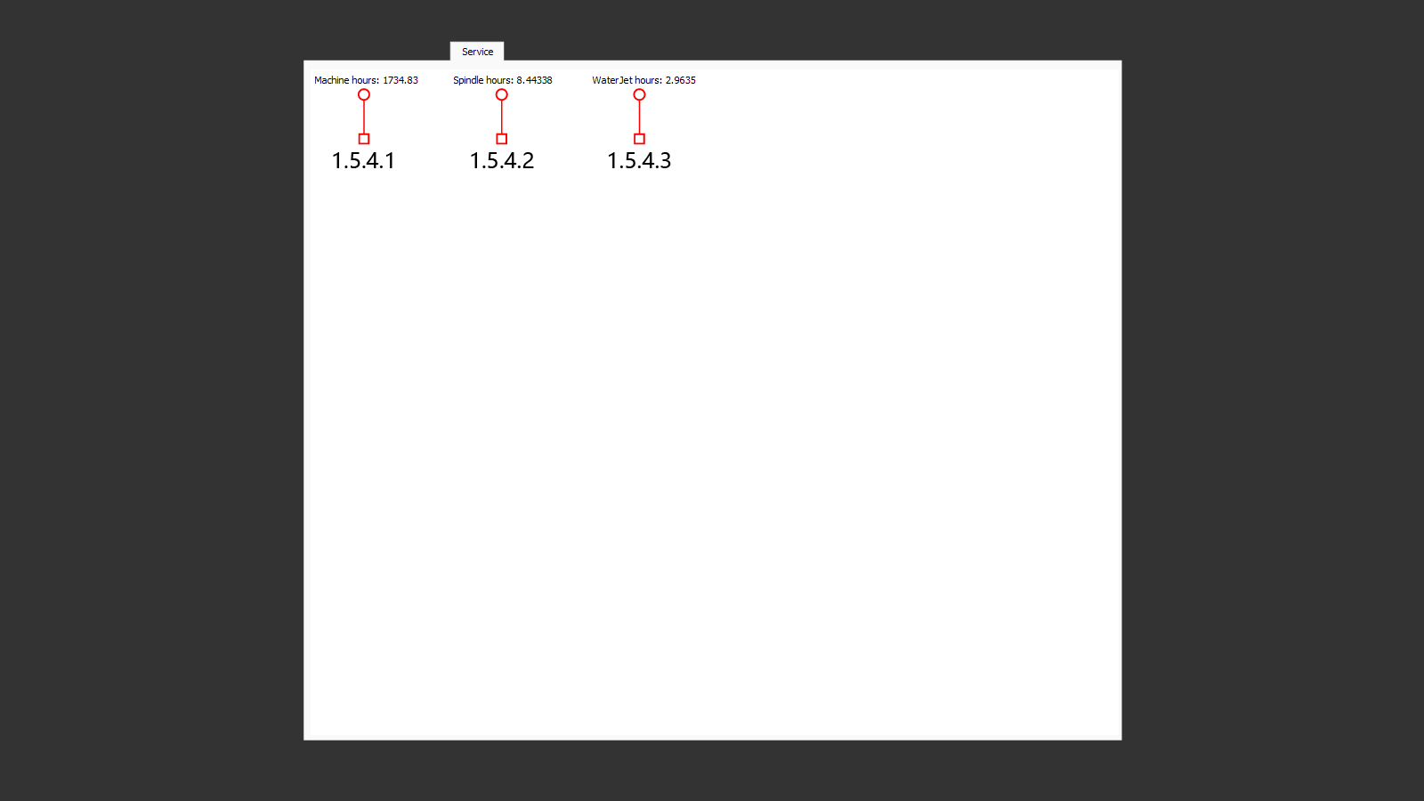
This section displays operational data for the machine and motors, including total running hours (machine hours), to facilitate timely maintenance.
¶ 1.5.4.1 Machine Hours
Displays the total runtime of the machine from its first activation to the most recent shutdown.
¶ 1.5.4.2 Spindle Hours
Shows the cumulative runtime of the spindle from its initial activation to the most recent shutdown.
¶ 1.5.4.3 Waterjet Hours
Indicates the total runtime of the waterjet motor from its first activation to the most recent shutdown.
¶ 1.6 Parameters
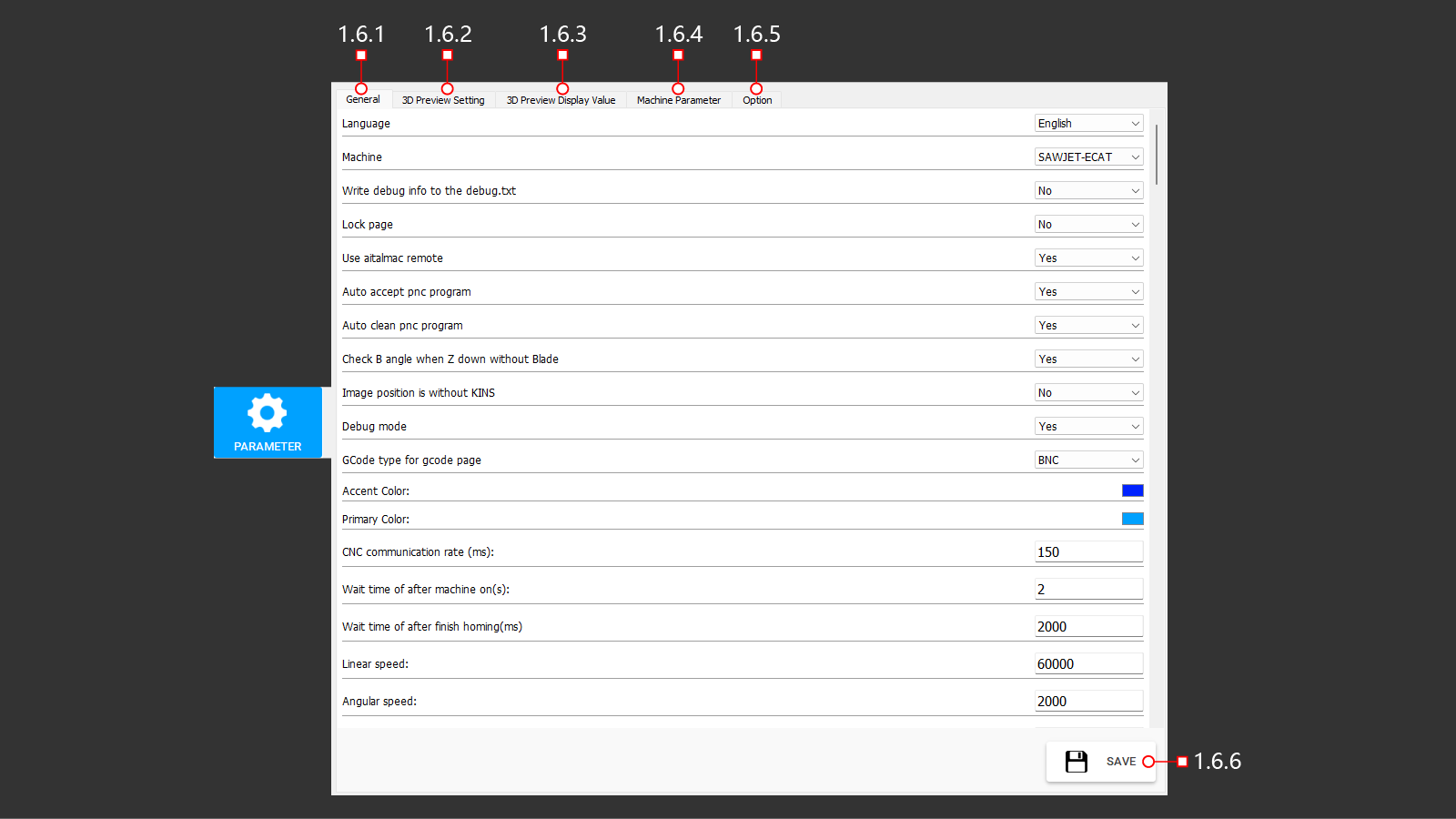
The main machine parameters are divided into five tabs for easy navigation and adjustment.
¶ 1.6.1 General (1-18)
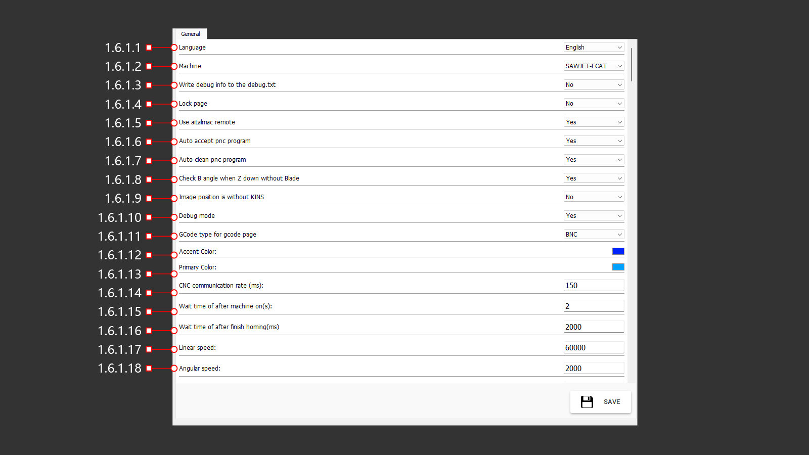
This tab contains the primary settings for the machine.
¶ 1.6.1.1 Language
Allows the selection of the interface language. Users can activate one of the available language options.
¶ 1.6.1.2 Machine
Enables the selection of the machine model for parameter configuration. Activate the appropriate model to adjust settings.
¶ 1.6.1.3 Write Debug Info To The Debug.txt
Enabling or disabling the "Write debug information to a file" debug.txt
¶ 1.6.1.4 Lock Page
Enabling or disabling the ability to block a page
¶ 1.6.1.5 Use AitalMAC Remote
Enables or disables the ability to use the AitalMAC remote control for machine operations.
¶ 1.6.1.6 Auto Accept Pnc Program
¶ 1.6.1.7 Auto Clean Pnc Program
¶ 1.6.1.8 Check B Angle When Z Down Without Blade
Enabling or disabling the ability check B angle when Z down without Blade
¶ 1.6.1.9 Image Position Is Without Kins
¶ 1.6.1.10 Debug Mode
¶ 1.6.1.11 Gcode Type For Gcode Page
Choosing the file format for downloading the G-code program
¶ 1.6.1.12 Accent Color
Selection of the accent color for display in the menu.
¶ 1.6.1.13 Primary Color
Selection of the primary color for display in the menu.
¶ 1.6.1.14 CNC Communication Rate (ms)
The communication speed of the control modules.
¶ 1.6.1.15 Wait Time After Machine On (s)
The waiting time before using the machine after it is turned on. This allows for self-testing and system checks.
¶ 1.6.1.16 Wait Time After Finish Homing (ms)
The waiting time after completing the homing sequence.
¶ 1.6.1.17 Linear Speed
The linear movement speed of the machine.
¶ 1.6.1.18 Angular Speed
The angular rotation speed of the machine.
¶ 1.6.1 General (19-34)
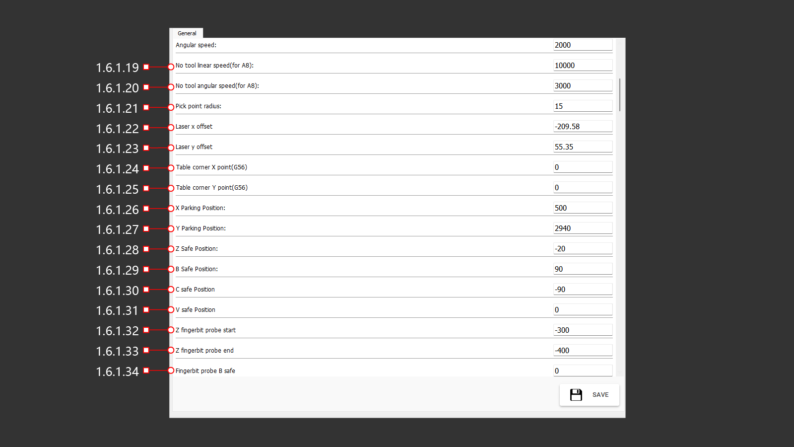
¶ 1.6.1.19 No Tool Linear Speed (for A8)
The linear movement speed of the machine when no tool is loaded.
¶ 1.6.1.20 No Tool Angular Speed (for A8)
The angular rotation speed of the machine when no tool is loaded.
¶ 1.6.1.21 Pick Point Radius
The radius of the point created as a marker (laser cross) in the imported file.
¶ 1.6.1.22 Laser X Offset
The laser's offset distance along the X-axis.
¶ 1.6.1.23 Laser Y Offset
The laser's offset distance along the Y-axis.
¶ 1.6.1.24 Table Corner X Point (G56)
The coordinate system selection for the table corner along the X-axis.
¶ 1.6.1.25 Table Corner Y Point (G56)
The coordinate system selection for the table corner along the Y-axis.
¶ 1.6.1.26 X Parking Position
The X-axis coordinates for parking the machine in a safe position.
¶ 1.6.1.27 Y Parking Position
The Y-axis coordinates for parking the machine in a safe position.
¶ 1.6.1.28 Z Safe Position
The safety position distance along the Z-axis.
¶ 1.6.1.29 B Safe Position
The safety position angle along the B-axis.
¶ 1.6.1.30 C Safe Position
The safety position angle along the C-axis.
¶ 1.6.1.31 V Safe Position
The safety position angle along the V-axis.
¶ 1.6.1.32 Z Fingerbit Probe Start
The Z-axis coordinate for the start of the slow descent to the probe for measuring the installed tool's length.
¶ 1.6.1.33 Z Fingerbit Probe End
The Z-axis coordinate for the end of the descent to the probe for measuring the installed tool's length.
¶ 1.6.1.34 Fingerbit Probe B Safe
The B-axis angle position for performing the tool length measurement command using the probe.
¶ 1.6.1 General (35-50)
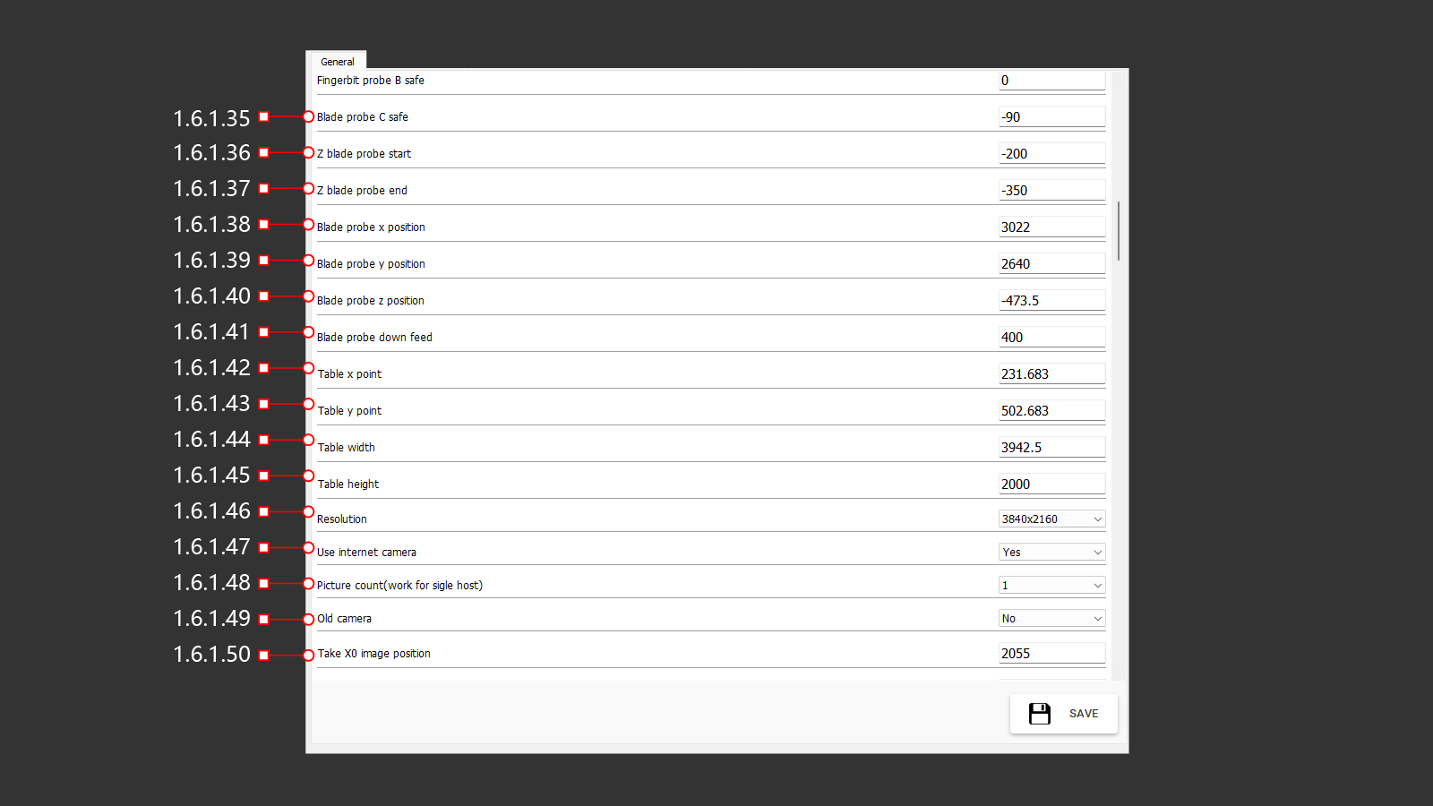
¶ 1.6.1.35 Blade Probe C Safe
The C-axis angle for performing the blade diameter measurement using the probe.
¶ 1.6.1.36 Z Blade Probe Start
The Z-axis coordinate for starting the slow descent of the machine head to the probe for measuring the blade diameter.
¶ 1.6.1.37 Z Blade Probe End
The Z-axis coordinate for ending the descent of the machine head to the probe for measuring the blade diameter.
¶ 1.6.1.38 Blade Probe X Position
The X-axis coordinate of the probe.
¶ 1.6.1.39 Blade Probe Y Position
The Y-axis coordinate of the probe.
¶ 1.6.1.40 Blade Probe Z Position
The Z-axis coordinate of the probe.
¶ 1.6.1.41 Blade Probe Down Feed
The feed rate for performing the blade diameter measurement.
¶ 1.6.1.42 Table X Point
The X-axis coordinate of the table corner point.
¶ 1.6.1.43 Table Y Point
The Y-axis coordinate of the table corner point.
¶ 1.6.1.44 Table Width
The width of the table.
¶ 1.6.1.45 Table Height
The height of the table.
¶ 1.6.1.46 Resolution
The tab for selecting image resolution.
¶ 1.6.1.47 Use Internet Camera
Enables or disables the use of a network camera.
¶ 1.6.1.48 Picture Count (work For Single Host)
Specifies the number of pictures to be taken.
¶ 1.6.1.49 Old Camera
Indicates whether the old camera is active or inactive.
¶ 1.6.1.50 Take X0 Image Position
The X-axis coordinate for taking a photo.
¶ 1.6.1 General (51-65)
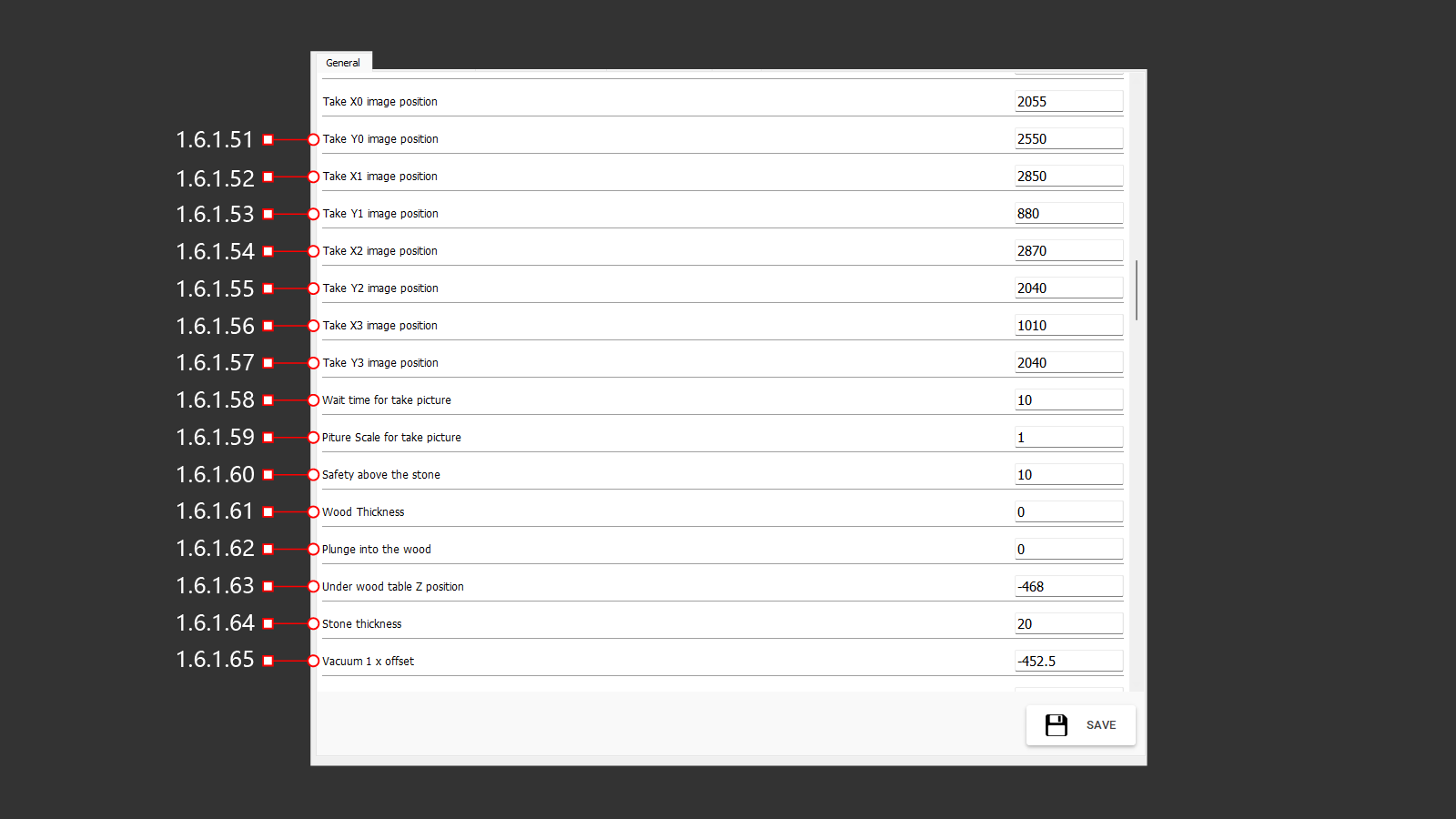
¶ 1.6.1.51 Take Y0 Image Position
The Y-axis coordinate for taking a photo.
¶ 1.6.1.52 Take X1 Image Position
The X-axis coordinate for taking a photo.
¶ 1.6.1.53 Take Yl Image Position
The Y-axis coordinate for taking a photo.
¶ 1.6.1.54 Take X2 Image Position
The X-axis coordinate for taking a photo.
¶ 1.6.1.55 Take Y2 Image Position
The Y-axis coordinate for taking a photo.
¶ 1.6.1.56 Take X3 Image Position
The X-axis coordinate for taking a photo.
¶ 1.6.1.57 Take Y3 Image Position
The Y-axis coordinate for taking a photo.
¶ 1.6.1.58 Wait Time For Take Picture
The waiting time for equipment preparation before taking a picture.
¶ 1.6.1.59 Picture Scale For Take Picture
The scale of the image for saving and importing.
¶ 1.6.1.60 Safety Above The Stone
The safety clearance above the material.
¶ 1.6.1.61 Wood Thickness
The thickness of the workbench surface.
¶ 1.6.1.62 Plunge Into The Wood
The depth of the cutting tool's plunge into the workbench.
¶ 1.6.1.63 Under Wood Table Z Position
The Z-axis coordinate for the position below the workbench.
¶ 1.6.1.64 Stone Thickness
The thickness of the stone material.
¶ 1.6.1.65 Vacuum 1 X Offset
The X-axis offset of vacuum cup 1 relative to the center of rotation.
¶ 1.6.1 General (66-81)
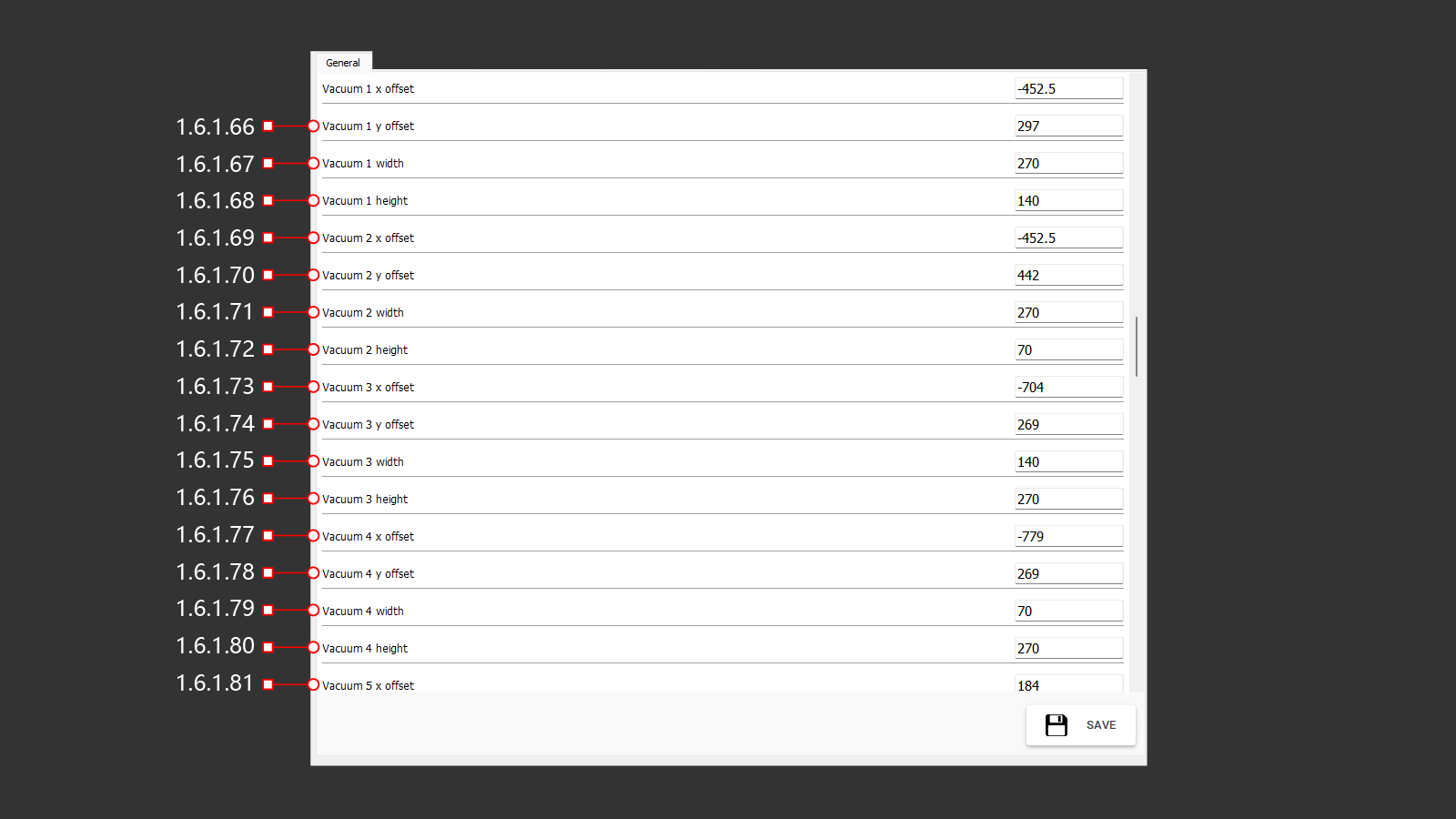
¶ 1.6.1.66 Vacuum 1 Y Offset
The Y-axis offset of vacuum cup 1 relative to the center of rotation.
¶ 1.6.1.67 Vacuum 1 Width
The width of vacuum cup 1.
¶ 1.6.1.68 Vacuum 1 Height
The height of vacuum cup 1.
¶ 1.6.1.69 Vacuum 2 X Offset
The X-axis offset of vacuum cup 2 relative to the center of rotation.
¶ 1.6.1.70 Vacuum 2 Y Offset
The Y-axis offset of vacuum cup 2 relative to the center of rotation.
¶ 1.6.1.71 Vacuum 2 Width
The width of vacuum cup 2.
¶ 1.6.1.72 Vacuum 2 Height
The height of vacuum cup 2.
¶ 1.6.1.73 Vacuum 3 X Offset
The X-axis offset of vacuum cup 3 relative to the center of rotation.
¶ 1.6.1.74 Vacuum 3 Y Offset
The Y-axis offset of vacuum cup 3 relative to the center of rotation.
¶ 1.6.1.75 Vacuum 3 Width
The width of vacuum cup 3.
¶ 1.6.1.76 Vacuum 3 Height
The height of vacuum cup 3.
¶ 1.6.1.77 Vacuum 4 X Offset
The X-axis offset of vacuum cup 4 relative to the center of rotation.
¶ 1.6.1.78 Vacuum 4 Y Offset
The Y-axis offset of vacuum cup 4 relative to the center of rotation.
¶ 1.6.1.79 Vacuum 4 Width
The width of vacuum cup 4.
¶ 1.6.1.80 Vacuum 4 Height
The height of vacuum cup 4.
¶ 1.6.1.81 Vacuum 5 X Offset
The X-axis offset of vacuum cup 5 relative to the center of rotation.
¶ 1.6.1 General (82-97)
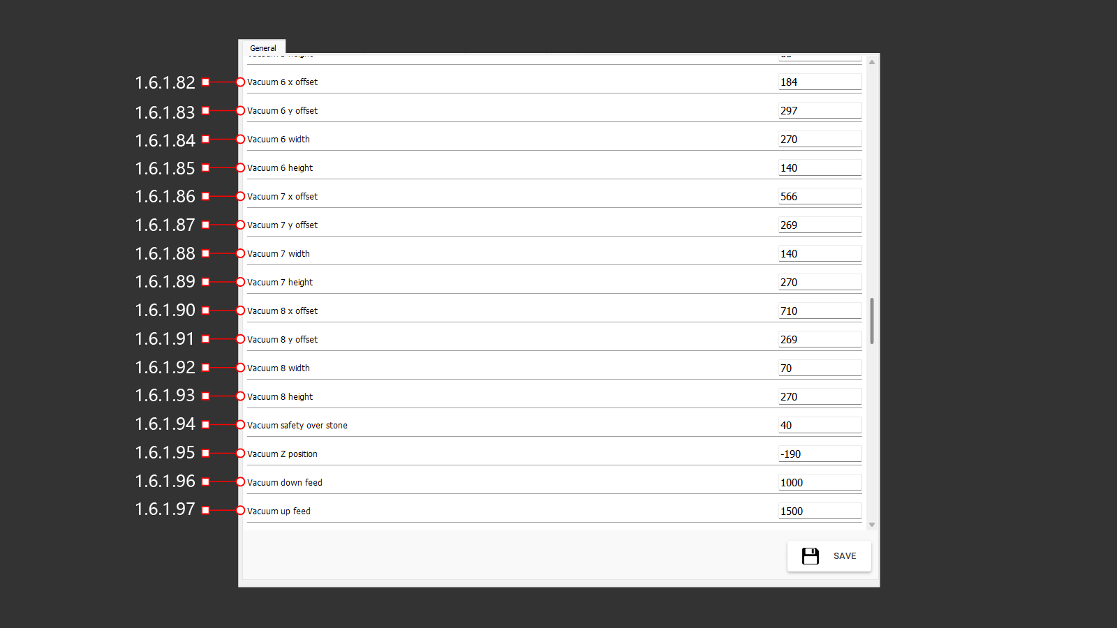
¶ 1.6.1.82 Vacuum 6 X Offset
The X-axis offset of vacuum cup 6 relative to the center of rotation.
¶ 1.6.1.83 Vacuum 6 Y Offset
The Y-axis offset of vacuum cup 6 relative to the center of rotation.
¶ 1.6.1.84 Vacuum 6 Width
The width of vacuum cup 6.
¶ 1.6.1.85 Vacuum 6 Height
The height of vacuum cup 6.
¶ 1.6.1.86 Vacuum 7 X Offset
The X-axis offset of vacuum cup 7 relative to the center of rotation.
¶ 1.6.1.87 Vacuum 7 Y Offset
The Y-axis offset of vacuum cup 7 relative to the center of rotation.
¶ 1.6.1.88 Vacuum 7 Width
The width of vacuum cup 7.
¶ 1.6.1.89 Vacuum 7 Height
The height of vacuum cup 7.
¶ 1.6.1.90 Vacuum 8 X Offset
The X-axis offset of vacuum cup 8 relative to the center of rotation.
¶ 1.6.1.91 Vacuum 8 Y Offset
The Y-axis offset of vacuum cup 8 relative to the center of rotation.
¶ 1.6.1.92 Vacuum 8 Width
The width of vacuum cup 8.
¶ 1.6.1.93 Vacuum 8 Height
The height of vacuum cup 8.
¶ 1.6.1.94 Vacuum Safety Over Stone
The safety clearance distance of vacuum cups above the stone material.
¶ 1.6.1.95 Vacuum Z Position
The Z-axis coordinate for the position of the vacuum cups.
¶ 1.6.1.96 Vacuum Down Feed
The feed rate for lowering the material using vacuum cups.
¶ 1.6.1.97 Vacuum Up Feed
The feed rate for raising the material using vacuum cups.
¶ 1.6.1 General (98-112)
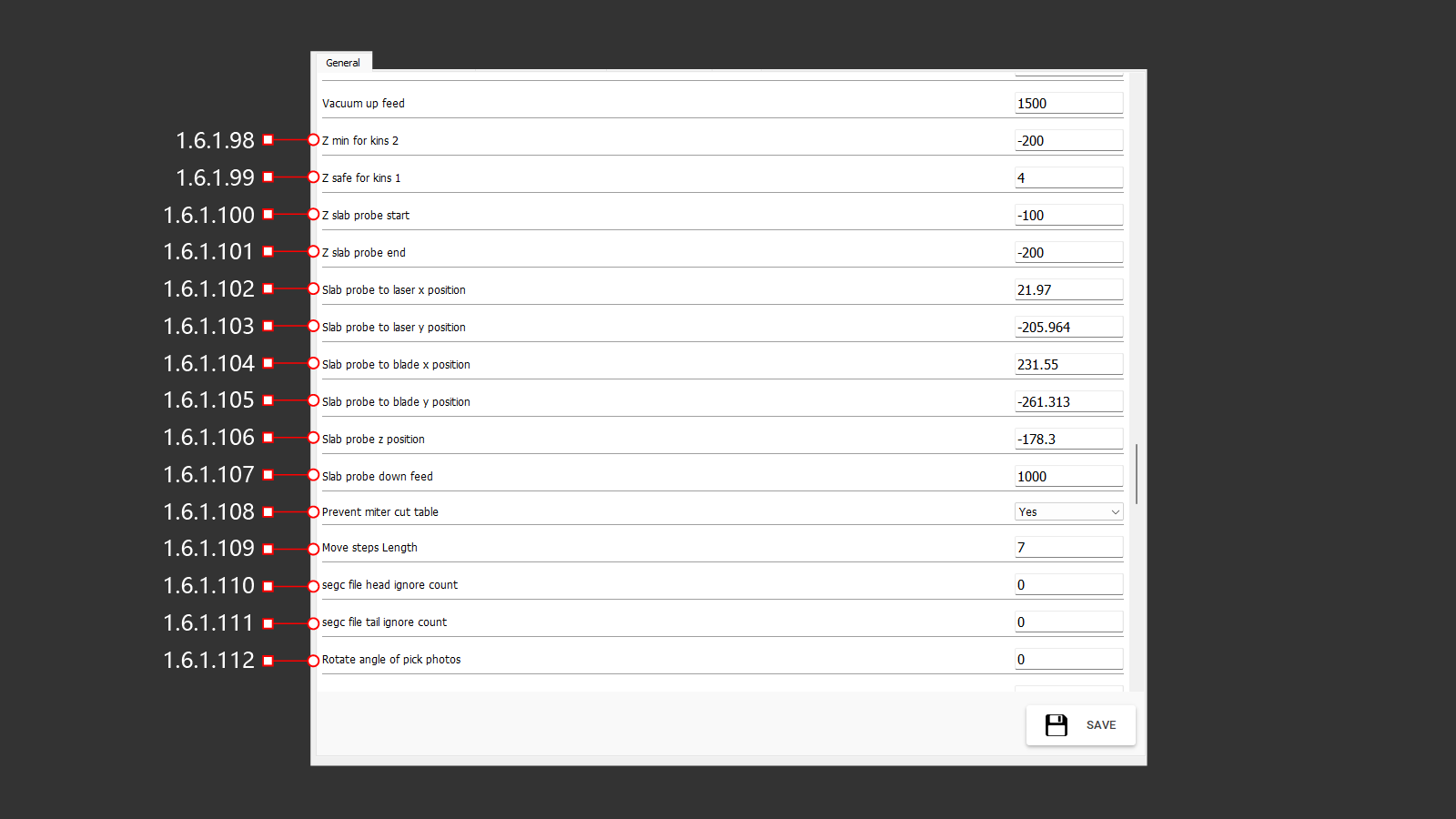
¶ 1.6.1.98 Z Min For Kins 2
The minimum Z-axis limit for Kinematics 2.
¶ 1.6.1.99 Z Safe For Kins 1
The safe Z-axis position for Kinematics 1.
¶ 1.6.1.100 Z Slab Probe Start
The Z-axis coordinate for starting the material thickness probe sequence.
¶ 1.6.1.101 Z Slab Probe End
The Z-axis coordinate for ending the material thickness probe sequence.
¶ 1.6.1.102 Slab Probe To Laser X Position
The X-axis offset between the slab probe and the laser cross position.
¶ 1.6.1.103 Slab Probe To Laser Y Position
The Y-axis offset between the slab probe and the laser cross position.
¶ 1.6.1.104 Slab Probe To Blade X Position
The X-axis offset between the slab probe and the blade.
¶ 1.6.1.105 Slab Probe To Blade Y Position
The Y-axis offset between the slab probe and the blade.
¶ 1.6.1.106 Slab Probe Z Position
The Z-axis coordinate for the slab probe's position during material thickness measurement.
¶ 1.6.1.107 Slab Probe Down Feed
The linear feed rate for lowering the slab probe during material thickness measurement.
¶ 1.6.1.108 Prevent Miter Cut Table
Enables or disables the prevention of cutting the workbench surface during operations with a tilted blade.
¶ 1.6.1.109 Move Steps Length
Specifies the length of incremental movements during manual operation.
¶ 1.6.1.110 SEGC File Head Ignore Count
The number of lines to ignore at the head of a SEGC file during import.
¶ 1.6.1.111 SEGC File Tail Ignore Count
The number of lines to ignore in the tail section of a SEGC file during import.
¶ 1.6.1.112 Rotate Angle Of Pick Photos
The rotation angle applied to photos during image capture.
¶ 1.6.1 General (113-127)
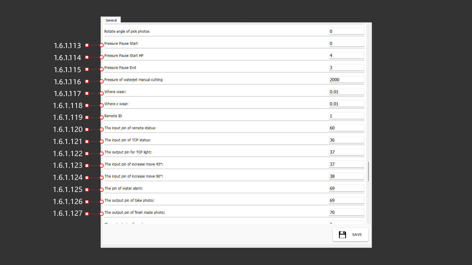
¶ 1.6.1.113 Pressure Pause Start
The waiting time for pressure buildup.
¶ 1.6.1.114 Pressure Pause Start HP
The waiting time for high-pressure buildup.
¶ 1.6.1.115 Pressure Pause End
The delay time before closing the valve after the pump stops operating.
¶ 1.6.1.116 Pressure Of Waterjet Manual Cutting
Sets the waterjet pressure for manual operations.
¶ 1.6.1.117 Where Wear
Correction value for tool wear.
¶ 1.6.1.118 Where Z Wear
Correction value for tool wear along the Z-axis.
¶ 1.6.1.119 Remote ID
The identification number for the remote control connection.
¶ 1.6.1.120 The Input Pin Of Remote Status
UI<=CNC Input Data Signal: Indicates the switch position of the remote control.
¶ 1.6.1.121 The Input Pin Of TCP Status
UI<=CNC Input Data Signal: Indicates the switch position for axis interpolation on the operator panel.
¶ 1.6.1.122 The Output Pin For TCP Light
UI=>CNC Output Signal: Indicates the activation of the axis interpolation switch light.
¶ 1.6.1.123 The Input Pin Of Increase Move 45°
UI<=CNC Input Data Signal: Detects the switch position for incrementally rotating the B axis by 45°.
¶ 1.6.1.124 The Input Pin Of Increase Move 90°
UI<=CNC Input Data Signal: Detects the switch position for incrementally rotating the B axis by 90°.
¶ 1.6.1.125 The Pin Of Water Alarm
UI<=CNC Input Data Signal: Indicates the absence of water pressure in the input pipeline of the machine.
¶ 1.6.1.126 The Output Pin Of Taking Photo
UI=>CNC Output Data Signal: Activates the camera action to take a photo of the material on the workbench.
¶ 1.6.1.127 The Output Pin Of Finish Made Photo
UI=>CNC Output Data Signal: Indicates that the camera has completed taking a photo of the material on the workbench.
¶ 1.6.1 General (128-142)
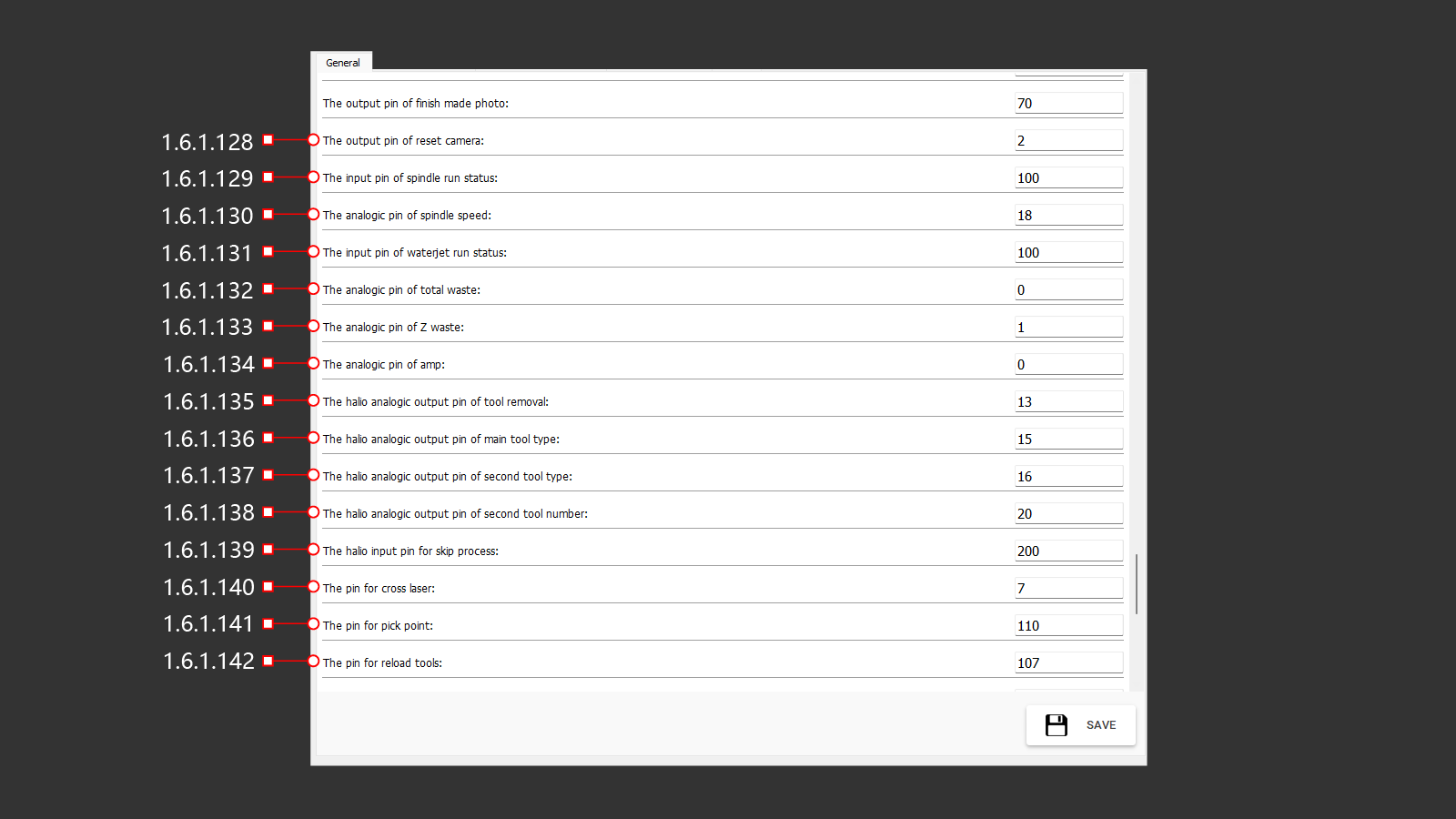
¶ 1.6.1.128 The Output Pin Of Reset Camera
UI<=CNC Input Data Signal: Indicates that the camera reset button has been pressed to reboot and reconnect the camera.
¶ 1.6.1.129 The Input Pin Of Spindle Run Status
UI<=CNC Input Data Signal: Indicates that the spindle is running and ready for operation.
¶ 1.6.1.130 The Analogic Pin Of Spindle Speed
Analog output pin directly transmits the spindle's rotation speed from the CNC digital output.
¶ 1.6.1.131 The Input Pin Of Waterjet Run Status
UI<=CNC Input Data Signal: Indicates that the waterjet pump is running and ready for operation.
¶ 1.6.1.132 The Analogic Pin Of Total Waste
¶ 1.6.1.133 The Analogic Pin Of Z Waste
¶ 1.6.1.134 The Analogic Pin Of Amp
Analog output pin directly transmits the spindle load (amps) from the CNC digital output.
¶ 1.6.1.135 The HALIO Analogic Output Pin Of Tool Removal
HALIO reference to the virtual interface signal. UI=>CNC Output Data Signal: Indicates the absence of a tool.
¶ 1.6.1.136 The HALIO Analogic Output Pin Of Main Tool Type
HALIO reference to the virtual interface signal. UI=>CNC Output Data Signal: Indicates the type of the main installed tool.
¶ 1.6.1.137 The HALIO Analogic Output Pin Of Second Tool Type
HALIO reference to the virtual interface signal. UI=>CNC Output Data Signal: Indicates the type of the second installed tool.
¶ 1.6.1.138 The HALIO Analogic Output Pin Of Second Tool Number
HALIO reference to the virtual interface signal. UI=>CNC Output Data Signal: Indicates the number of the second installed tool.
¶ 1.6.1.139 The HALIO Input Pin For Skip Process
HALIO reference to the virtual interface signal. UI<=CNC Input Data Signal: ????
¶ 1.6.1.140 The Pin For Cross Laser
UI<=CNC Input Data Signal: Indicates the activation and usage of the cross laser.
¶ 1.6.1.141 The Pin For Pick Point
UI<=CNC Input Data Signal: Indicates the retrieval of a point from the cross laser's position.
¶ 1.6.1.142 The Pin For Reload Tools
UI<=CNC Input Data Signal: Indicates the need to change the installed tool to complete the operation.
¶ 1.6.1 General (143-156)
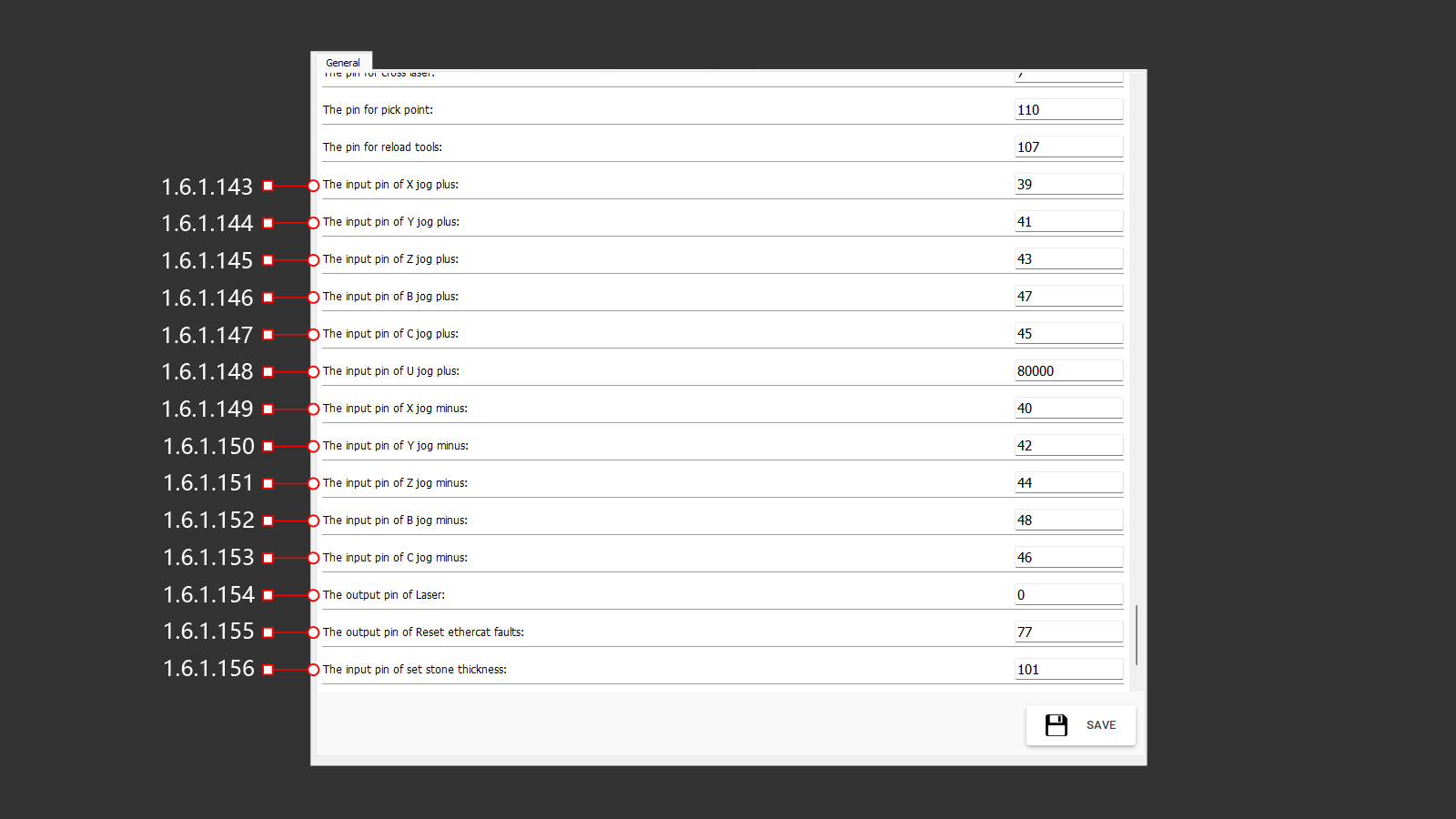
¶ 1.6.1.143 The Input Pin Of X Jog Plus
UI<=CNC Input Data Signal: Incremental jog movement in the positive X-axis direction.
¶ 1.6.1.144 The Input Pin Of Y Jog Plus
UI<=CNC Input Data Signal: Incremental jog movement in the positive Y-axis direction.
¶ 1.6.1.145 The Input Pin Of Z Jog Plus
UI<=CNC Input Data Signal: Incremental jog movement in the positive Z-axis direction.
¶ 1.6.1.146 The Input Pin Of B Jog Plus
UI<=CNC Input Data Signal: Incremental jog movement in the positive B-axis direction.
¶ 1.6.1.147 The Input Pin Of C Jog Plus
UI<=CNC Input Data Signal: Incremental jog movement in the positive C-axis direction.
¶ 1.6.1.148 The Input Pin Of U Jog Plus
UI<=CNC Input Data Signal: Incremental jog movement in the positive U-axis direction.
¶ 1.6.1.149 The Input Pin Of X Jog Minus
UI<=CNC Input Data Signal: Incremental jog movement in the negative X-axis direction.
¶ 1.6.1.150 The Input Pin Of Y Jog Minus
UI<=CNC Input Data Signal: Incremental jog movement in the negative Y-axis direction.
¶ 1.6.1.151 The Input Pin Of Z Jog Minus
UI<=CNC Input Data Signal: Incremental jog movement in the negative Z-axis direction.
¶ 1.6.1.152 The Input Pin Of B Jog Minus
UI<=CNC Input Data Signal: Incremental jog movement in the negative B-axis direction.
¶ 1.6.1.153 The Input Pin Of C Jog Minus
UI<=CNC Input Data Signal: Incremental jog movement in the negative C-axis direction.
¶ 1.6.1.154 The Output Pin Of Laser
UI=>CNC Output Data Signal: Indicates the activation of the laser line.
¶ 1.6.1.155 The Output Pin Of Reset Ethercat Faults
UI<=CNC Input Data Signal: Indicates that the operator has reset the EtherCAT faults.
¶ 1.6.1.156 The Input Pin Of Set Stone Thickness
UI<=CNC Input Data Signal: Indicates the stone thickness value set in the parameters.
¶ 1.6.1 General (157-159)
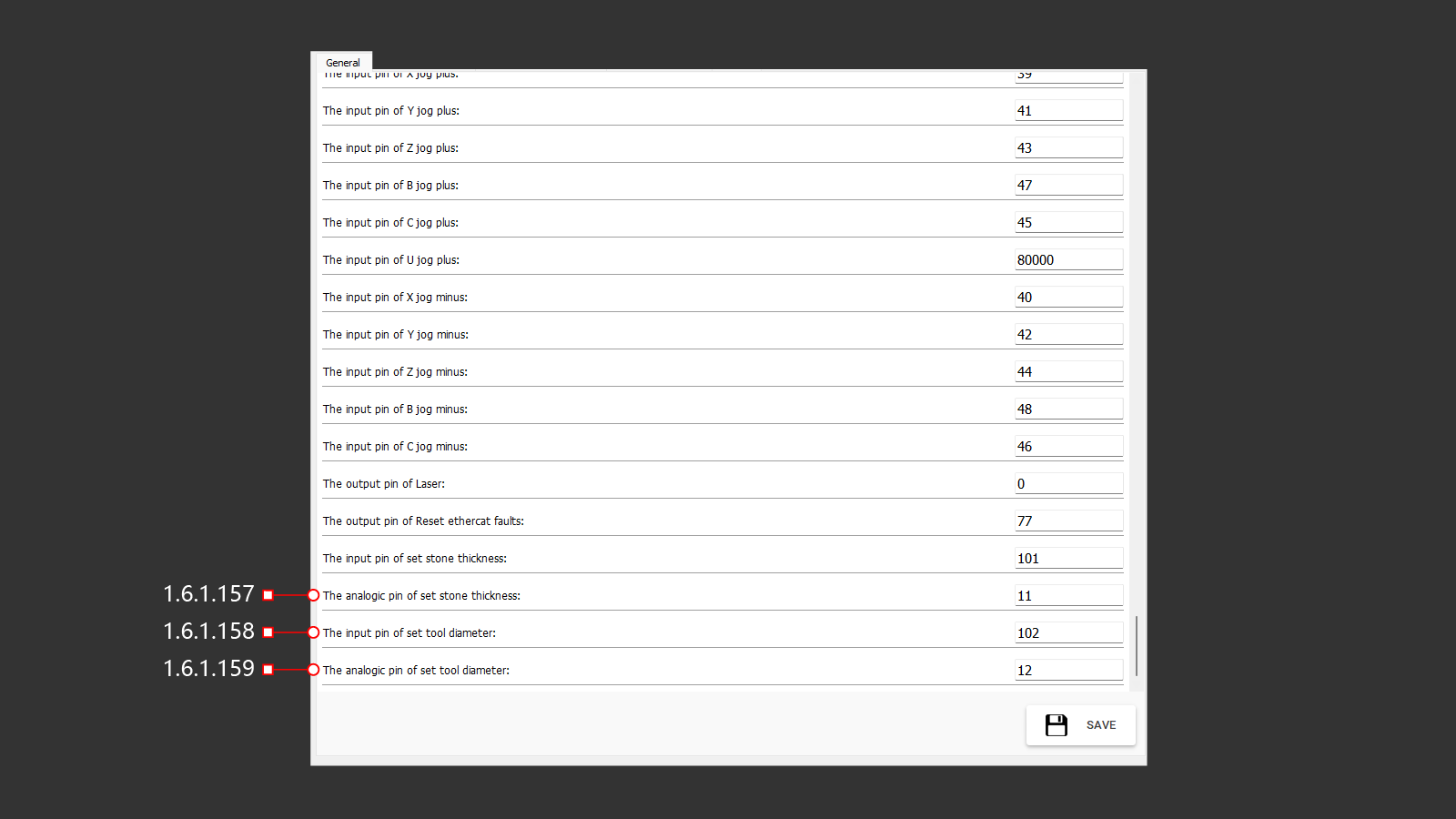
¶ 1.6.1.157 The Analogic Pin Of Set Stone Thickness
Analog output directly receiving the stone thickness value from the CNC after probing.
¶ 1.6.1.158 The Input Pin Of Set Tool Diameter
UI<=CNC Input Data Signal: Indicates the tool diameter set in the parameters.
¶ 1.6.1.159 The Analogic Pin Of Set Tool Diameter
Analog output directly receiving the tool diameter value from the CNC after probing.
¶ 1.6.1 General (160-162)
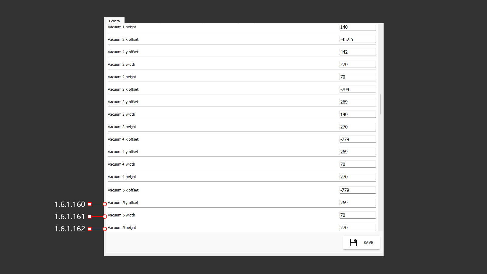
¶ 1.6.1.160 Vacuum 5 Y Offset
The Y-axis offset of vacuum cup 5 relative to the center of rotation.
¶ 1.6.1.161 Vacuum 5 Width
The width of vacuum cup 5.
¶ 1.6.1.162 Vacuum 5 Height
The height of vacuum cup 7.
¶ 1.6.2 3D Preview Setting
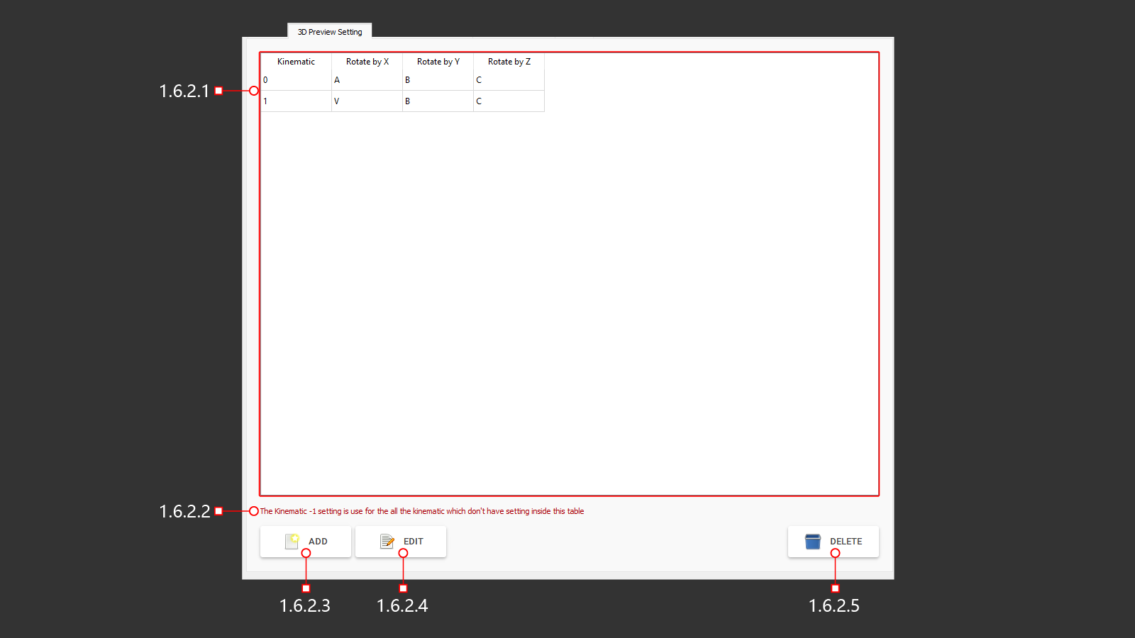
Settings for the 3D preview format.
¶ 1.6.2.1 List Of Kinematics
A list of elements for configuring the machine's kinematics.
¶ 1.6.2.2 Kinematics Warning
A warning related to the machine's kinematics configuration elements.
¶ 1.6.2.3 Add
Button for adding an additional parameter row.
¶ 1.6.2.4 Edit
Button for editing parameter rows.
¶ 1.6.2.5 Delete
Button for deleting the selected parameter row.
¶ 1.6.2.3 Dialog - Kinematics
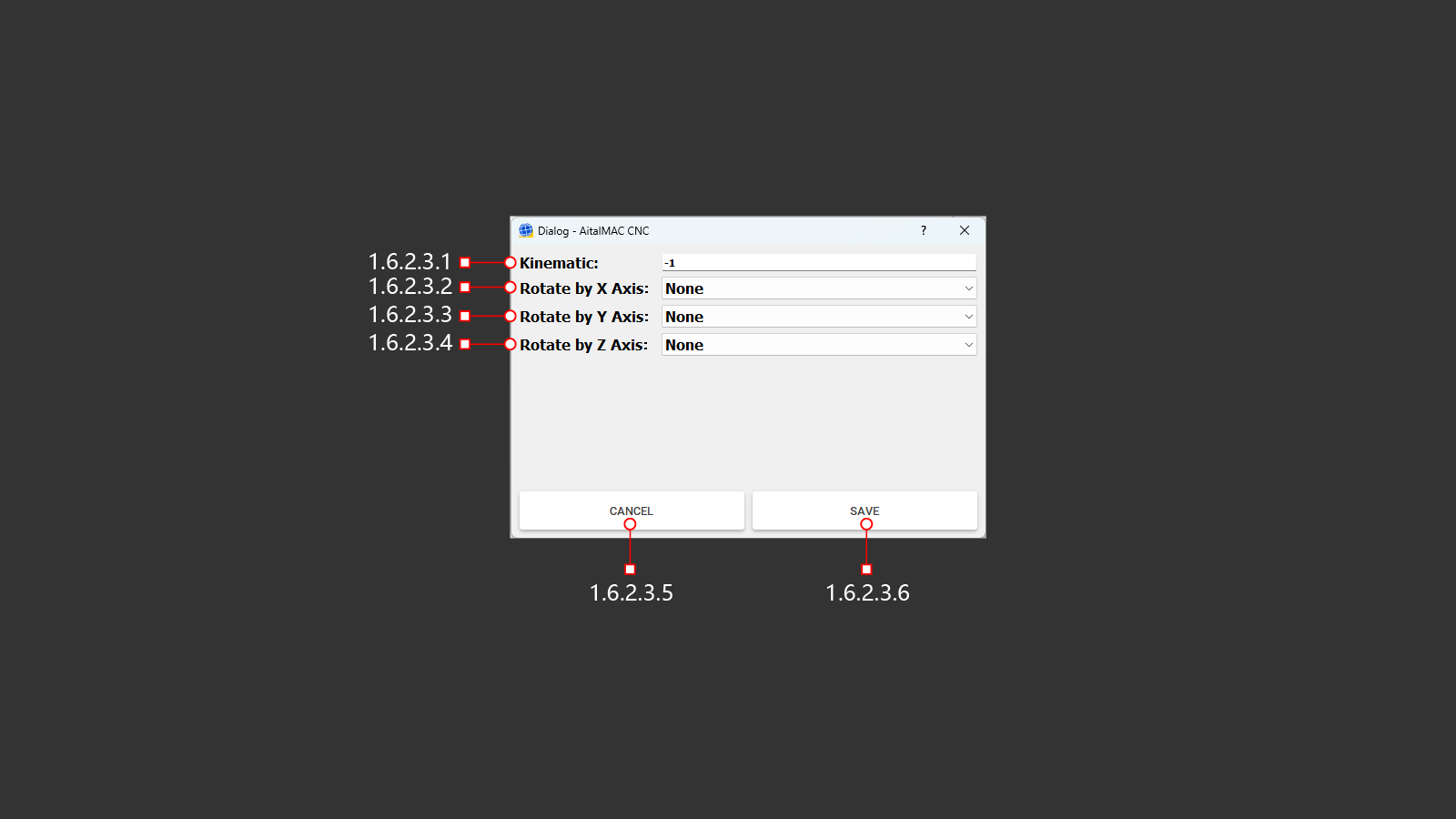
¶ 1.6.2.3.1 Kinematics
Specifies the table number for kinematics configuration (-1 by default).
¶ 1.6.2.3.2 Rotate By X Axis
Selects the value for rotation around the X-axis (not assigned).
¶ 1.6.2.3.3 Rotate By Y Axis
Selects the value for rotation around the Y-axis (not assigned).
¶ 1.6.2.3.4 Rotate By Z Axis
Selects the value for rotation around the Z-axis (not assigned).
¶ 1.6.2.3.5 Cancel
Cancels the changes made to the configuration settings.
¶ 1.6.2.3.6 Save
Saves the changes made to the configuration settings.
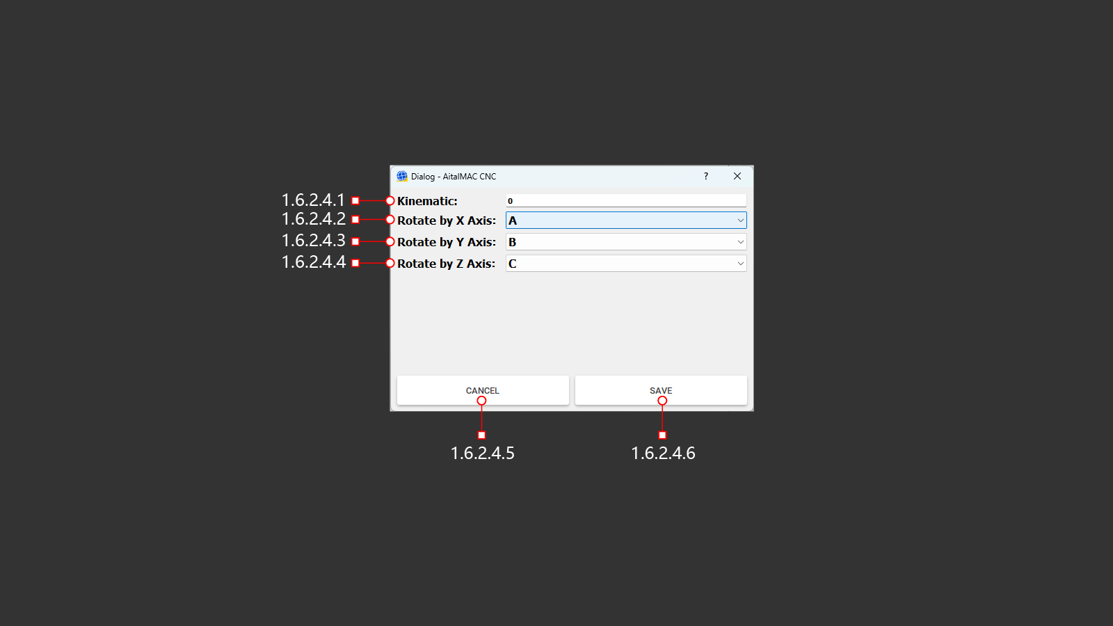
¶ 1.6.2.4.1 Kinematics
Specifies the table number for kinematics configuration (default is 0).
¶ 1.6.2.4.2 Rotate By X Axis
Selects the value (A) for rotation around the X-axis.
¶ 1.6.2.4.3 Rotate By Y Axis
Selects the value (B) for rotation around the Y-axis.
¶ 1.6.2.4.4 Rotate By Z Axis
Selects the value (C) for rotation around the Z-axis.
¶ 1.6.2.4.5 Cancel
Cancels the changes made to the configuration settings.
¶ 1.6.2.4.6 Save
Saves the changes made to the configuration settings.
¶ 1.6.3 3D Preview Display Value
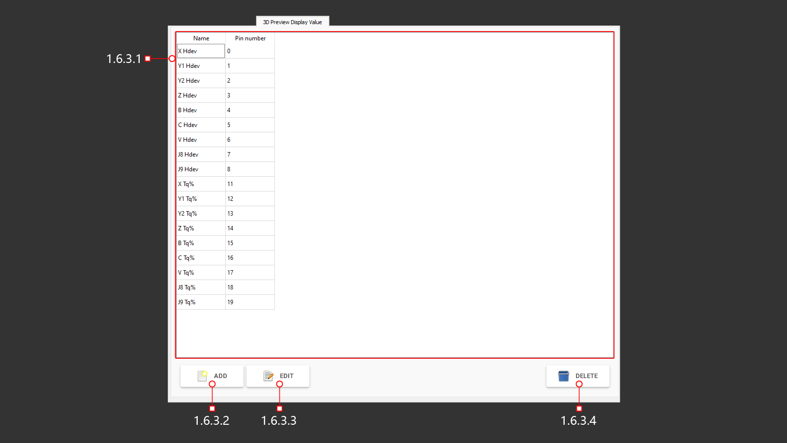
Значение отображения в 3D окне предварительного просмотра.
¶ 1.6.3.1 List Of Values For The 3D Preview
Список отображаемых значений в 3D окне предварительного просмотра.
¶ 1.6.3.2 Add
Добавление новое значения в список для отображения.
¶ 1.6.3.3 Edit
Редактирование выбранного значения.
¶ 1.6.3.4 Delete
Удаление выбранного значения.
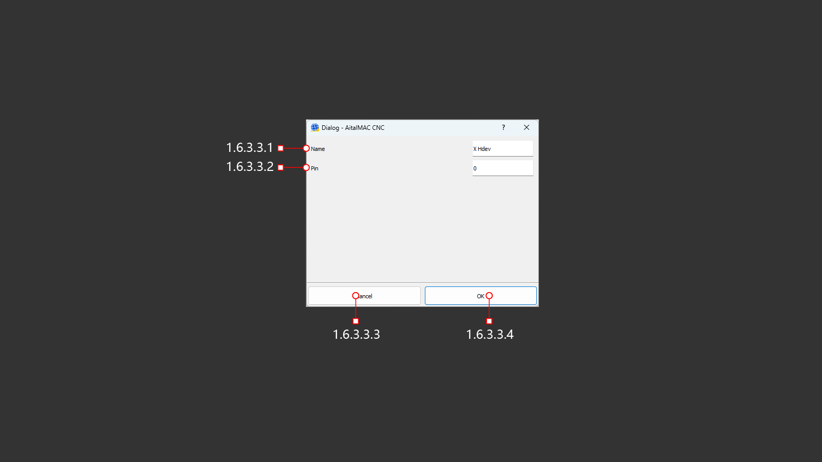
¶ 1.6.3.2.1 Name
Имя редактируемого значения.
¶ 1.6.3.2.2 Pin
Аналоговый выход для получения значений от ЧПУ.
¶ 1.6.3.2.3 Cancel
Отменить сделанные изменения.
¶ 1.6.3.2.4 OK
Сохранит сделаные изменения.
¶ 1.6.4 Machine Parameter
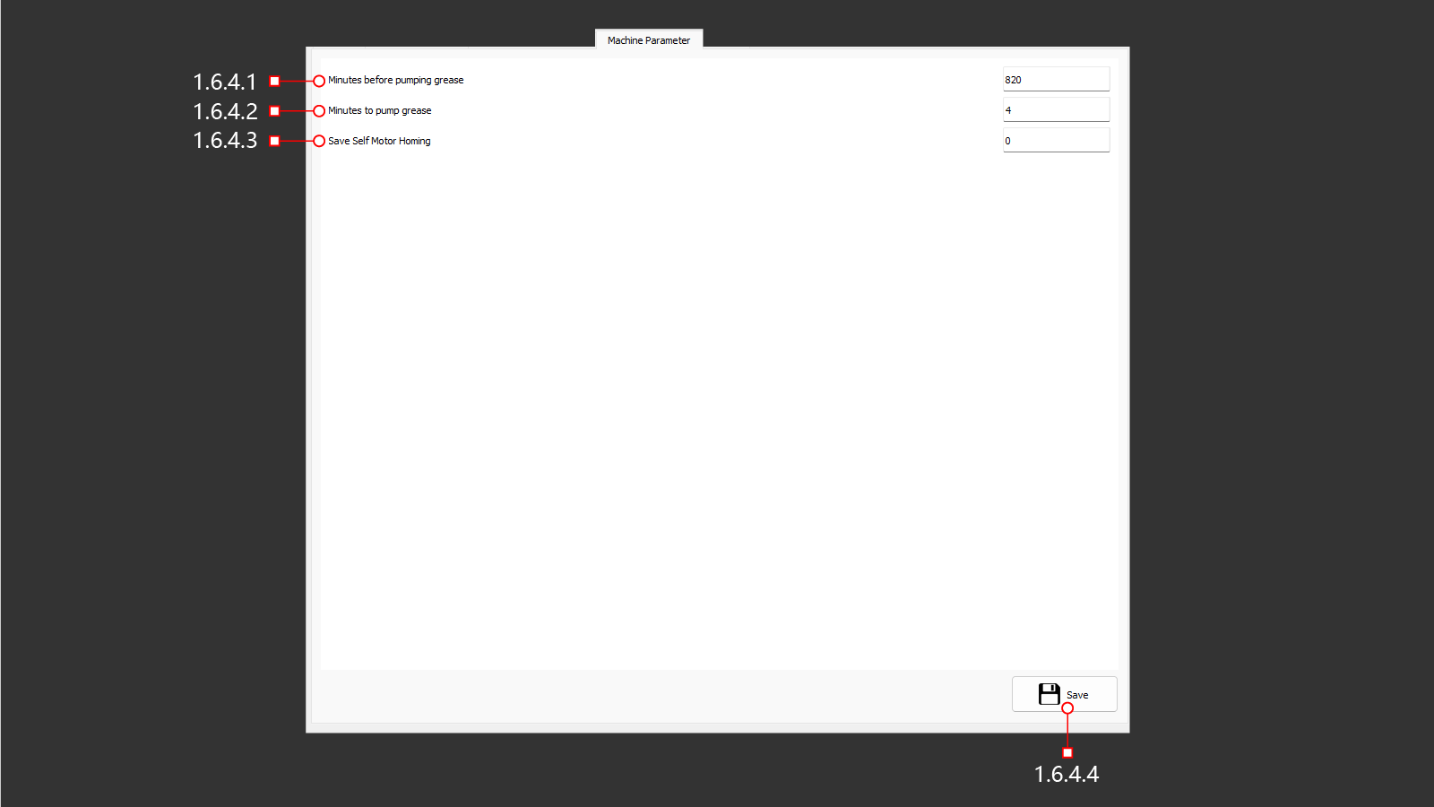
Параметры станка (обслуживание и настройка).
¶ 1.6.4.1 Minutes Before Pumping Grease
Промежуток времени между включения насоса для автоматической смазка станка.
¶ 1.6.4.2 Minutes To Pump Grease
Время работы насоса автоматической смазки.
¶ 1.6.4.3 Save Self Motor Homing
0 - Сохраненная позиция самонастройки станка по осям
1 – Создание новой настройки самонаведения станка по осям
¶ 1.6.4.4 Save
Сохранение выполненных изменений.
¶ 1.6.5 Option
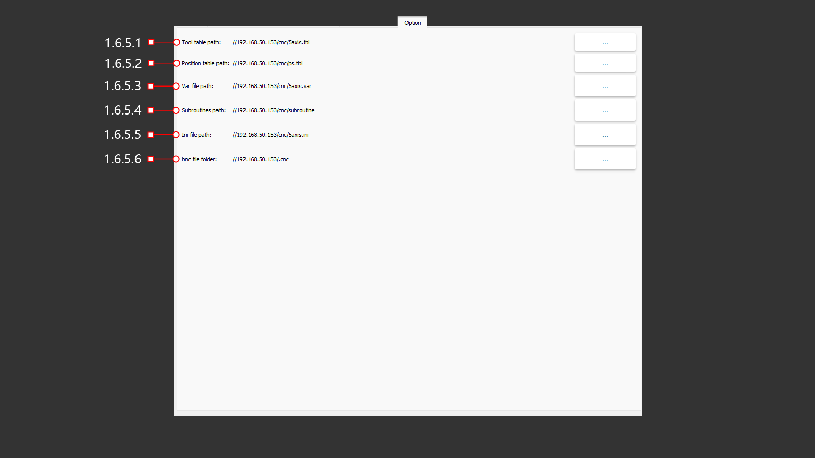
¶ 1.6.5.1 Tool Table Path
Путь (сетевой адрес) к таблице инструментов на ЧПУ.
¶ 1.6.5.2 Position Table Path
Путь (сетевой адрес) к таблице позиций на ЧПУ.
¶ 1.6.5.3 Var File Path
Путь (сетевой адрес) к файлу переменных на ЧПУ.
¶ 1.6.5.4 Subroutine Path
Путь (сетевой адрес) к подпрограммам на ЧПУ.
¶ 1.6.5.5 Ini File Path
Путь (сетевой адрес) к файлу Ini на ЧПУ.
¶ 1.6.5.6 Bnc File Folder
Файловая папка bnc (сетевой адрес) на ЧПУ.
¶ 1.7 Tools
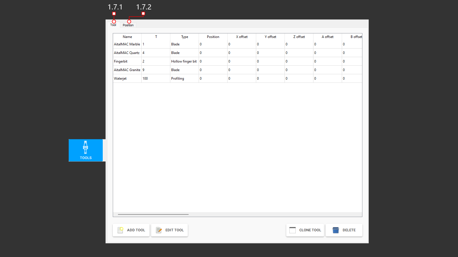
Панель инструментов, в памяти станка для выполнения работы.
¶ 1.7.1 Tool Tab
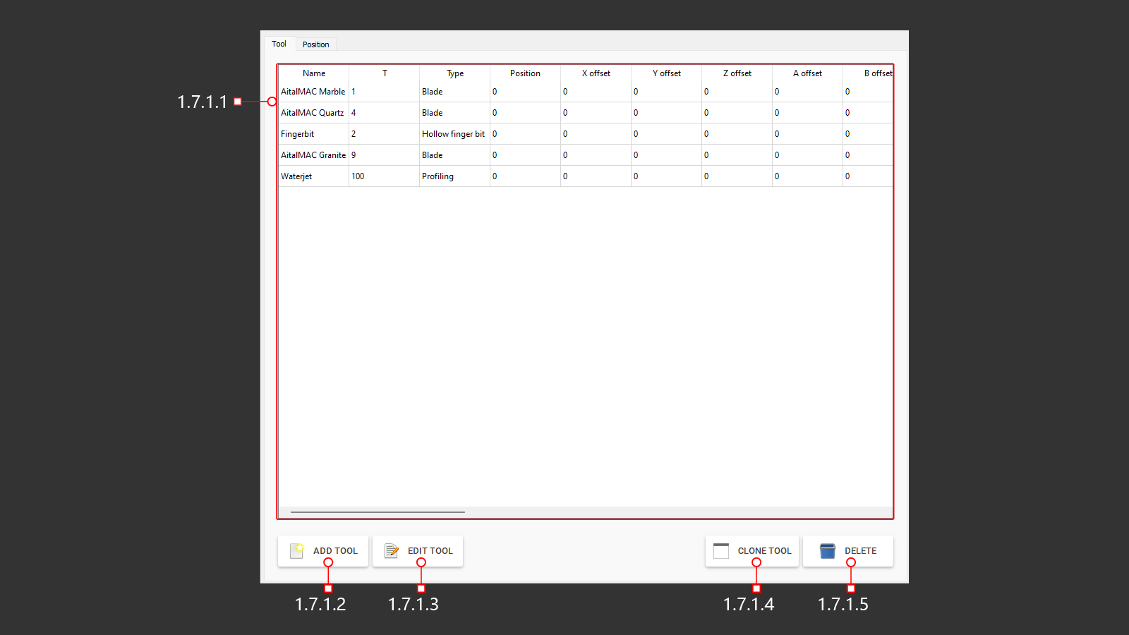
¶ 1.7.1.1 Tools List
Панель для добавления инструментов, в память станка для работы.
¶ 1.7.1.2 Add Tool
Добавление инструмента в память станка.
¶ 1.7.1.3 Edit Tool
Редактировать данные выбранного ранее созданного инструмента.
¶ 1.7.1.4 Clone Tool
Клонировать выбранный инструмент со всеми настройками.
¶ 1.7.1.5 Delete
Кнопка уданелия выбранного в таблице инструмента.
¶ 1.7.2 Position tab
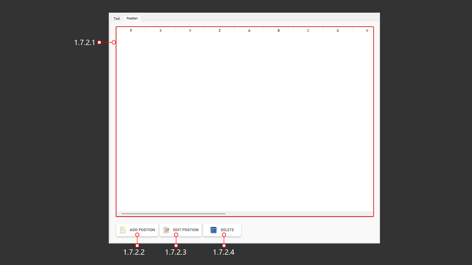
Панель для просмотра позиции инструмента, в памяти станка для выполнения автоматической смены инструмента.
¶ 1.7.2.1 Position List
Панель для добавления позиции инструмента в магазин автоматической смены, в памяти станка для выполнения работ.
¶ 1.7.2.2 Add Position
Добавление новой позиции в магазин инструмента.
¶ 1.7.2.3 Edit Position
Редактирование выбраной позиции инструмента в магазине.
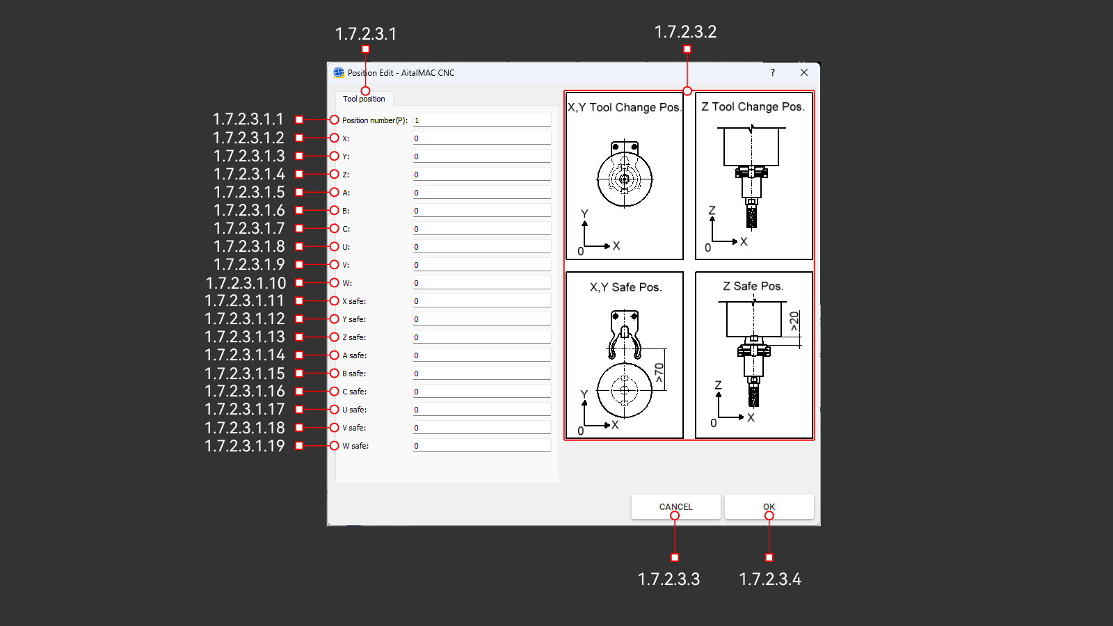
¶ 1.7.2.3.1 Tool Position Tab
Вкладка с параметрами для настройки позиции инструманта в магазине.
¶ 1.7.2.3.1.1 Position Number(p)
Номер позиции в магазине инструмента для которого необходимо выпорнить настройку.
¶ 1.7.2.3.1.2 X
Координата по оси Х, когда конус (ISO) с инструментом находится в шпинделе, а также зафиксирован в держателе инструмента в магазине.
¶ 1.7.2.3.1.3 Y
Координата по оси Y, когда конус (ISO) с инструментом находится в шпинделе, а также зафиксирован в держателе инструмента в магазине.
¶ 1.7.2.3.1.4 Z
Координата по оси Y, когда конус (ISO) с инструментом находится в шпинделе, а также зафиксирован в держателе инструмента в магазине.
¶ 1.7.2.3.1.5 A
Координата по оси A, когда конус (ISO) с инструментом находится в шпинделе, а также зафиксирован в держателе инструмента в магазине.
¶ 1.7.2.3.1.6 B
Координата по оси B, когда конус (ISO) с инструментом находится в шпинделе, а также зафиксирован в держателе инструмента в магазине.
¶ 1.7.2.3.1.7 C
Координата по оси C, когда конус (ISO) с инструментом находится в шпинделе, а также зафиксирован в держателе инструмента в магазине.
¶ 1.7.2.3.1.8 U
Координата по оси U, когда конус (ISO) с инструментом находится в шпинделе, а также зафиксирован в держателе инструмента в магазине.
¶ 1.7.2.3.1.9 V
Координата по оси V, когда конус (ISO) с инструментом находится в шпинделе, а также зафиксирован в держателе инструмента в магазине.
¶ 1.7.2.3.1.10 W
Координата по оси W, когда конус (ISO) с инструментом находится в шпинделе, а также зафиксирован в держателе инструмента в магазине.
¶ 1.7.2.3.1.11 X Safe
Координата безопасного положения по оси Х, когда станок переходит на пониженную подачу для смены или захвата инструмента в магазине.
¶ 1.7.2.3.1.12 Y Safe
Координата безопасного положения по оси Y, когда станок переходит на пониженную подачу для смены или захвата инструмента в магазине.
¶ 1.7.2.3.1.13 Z Safe
Координата безопасного положения по оси Z, когда станок переходит на пониженную подачу для смены или захвата инструмента в магазине.
¶ 1.7.2.3.1.14 A Safe
Координата безопасного положения по оси A, когда станок переходит на пониженную подачу для смены или захвата инструмента в магазине.
¶ 1.7.2.3.1.15 B Safe
Координата безопасного положения по оси B, когда станок переходит на пониженную подачу для смены или захвата инструмента в магазине.
¶ 1.7.2.3.1.16 C Safe
Координата безопасного положения по оси C, когда станок переходит на пониженную подачу для смены или захвата инструмента в магазине.
¶ 1.7.2.3.1.17 U Safe
Координата безопасного положения по оси U, когда станок переходит на пониженную подачу для смены или захвата инструмента в магазине.
¶ 1.7.2.3.1.18 V Safe
Координата безопасного положения по оси V, когда станок переходит на пониженную подачу для смены или захвата инструмента в магазине.
¶ 1.7.2.3.1.19 W Safe
Координата безопасного положения по оси W, когда станок переходит на пониженную подачу для смены или захвата инструмента в магазине.
¶ 1.7.2.3.2 Tool Change Position Figure
Изображение для наглядного отображения редактируемый координат для создания позиции смены инструмента в магазине.
¶ 1.7.2.3.3 Cancel
Отмена внесенных данных.
¶ 1.7.2.3.4 OK
Сохранение внесенных данных.
¶ 1.7.2.4 Delete
Удаление выбранной позиции.
¶ 1.8 Others
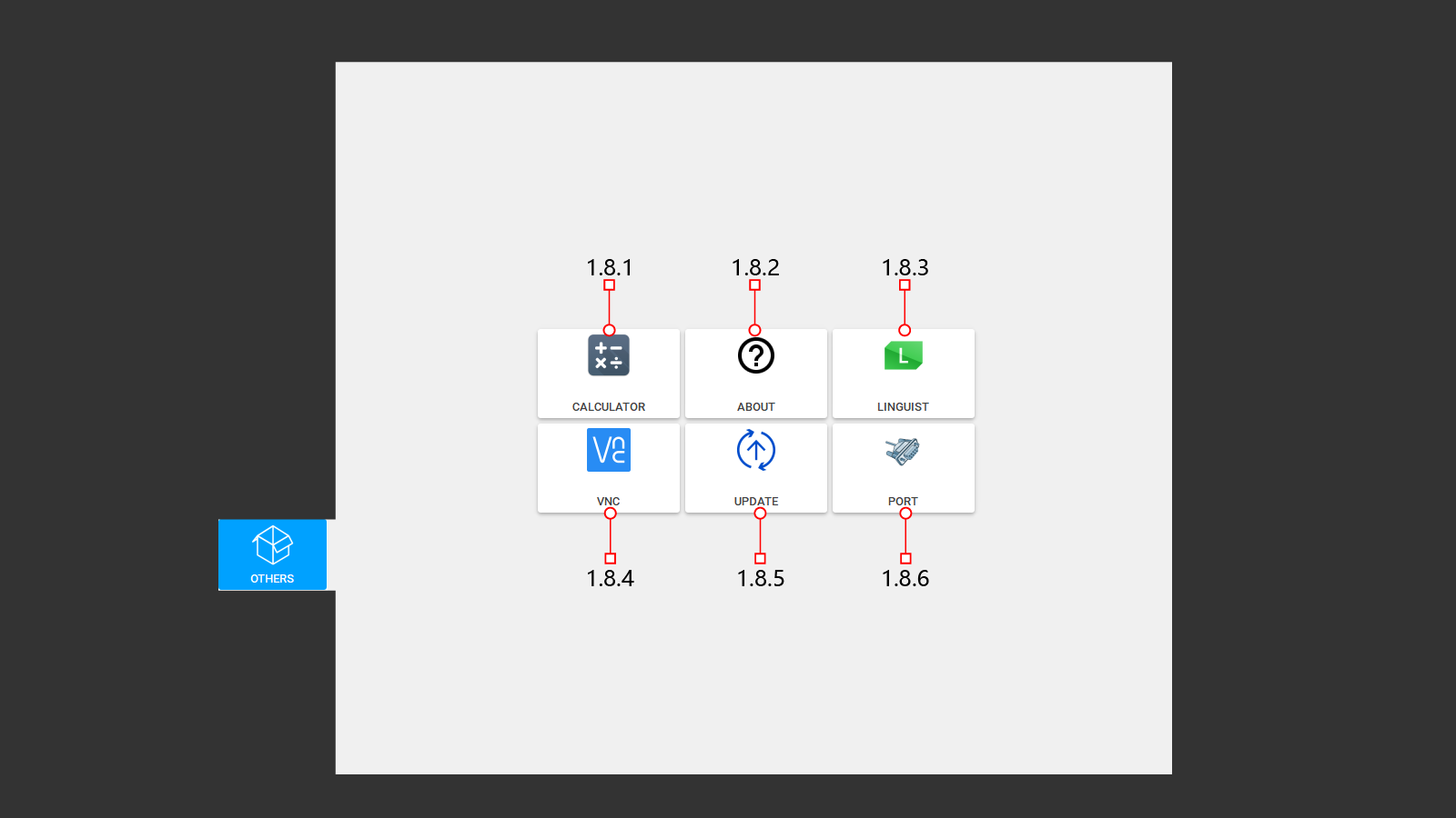
Остальное дополнитеное меню пользовательских настроек.
¶ 1.8.1 Calculator
Калькулятор.
¶ 1.8.2 About
Соглашение и версия установленного ПО.
¶ 1.8.2.1 OK
Ознакомиться и выйти.
¶ 1.8.3 Linguist
Редактор языка.
¶ 1.8.3.1 Linguist
¶ 1.8.3.2 Linguist With English
¶ 1.8.3.3 Linguist With Chinese
¶ 1.8.3.4 Linguist With Italian
¶ 1.8.4 VNC
¶ 1.8.4.1 VNC
Система удаленного доступа к рабочему столу компьютера по сети.
¶ 1.8.4.2 CNC: IP
Сетевой адрес удаленного компьютера.
¶ 1.8.5 Update
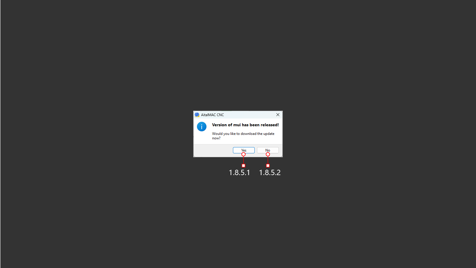
Обновление програмнного обеспечения.
¶ 1.8.5.1 Yes
Обновить ПО.
¶ 1.8.5.2 No
Не обновлять ПО.
¶ 1.8.6 Port
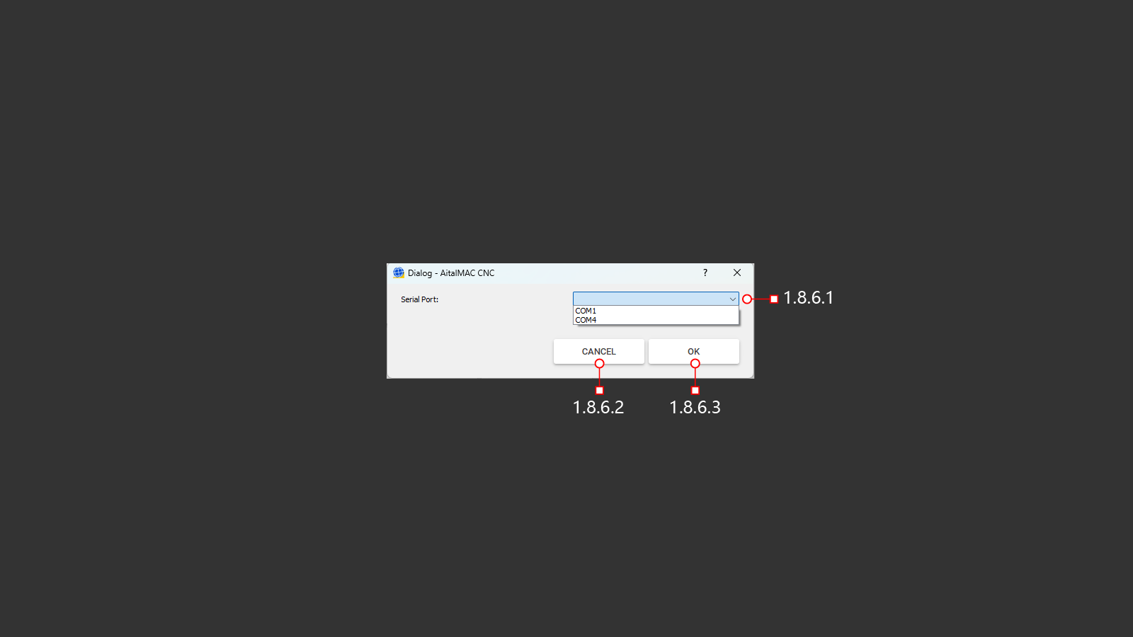
Порт для связи пульта дистанционного управления со станком.
¶ 1.8.6.1 Port List
Выбор порта для установки связи.
¶ 1.8.6.2 Cancel
Отменить изменения.
¶ 1.8.6.3 OK
Сохранить изменения.
¶ 1.9 Machine
¶ 1.10 Status And Control Panel
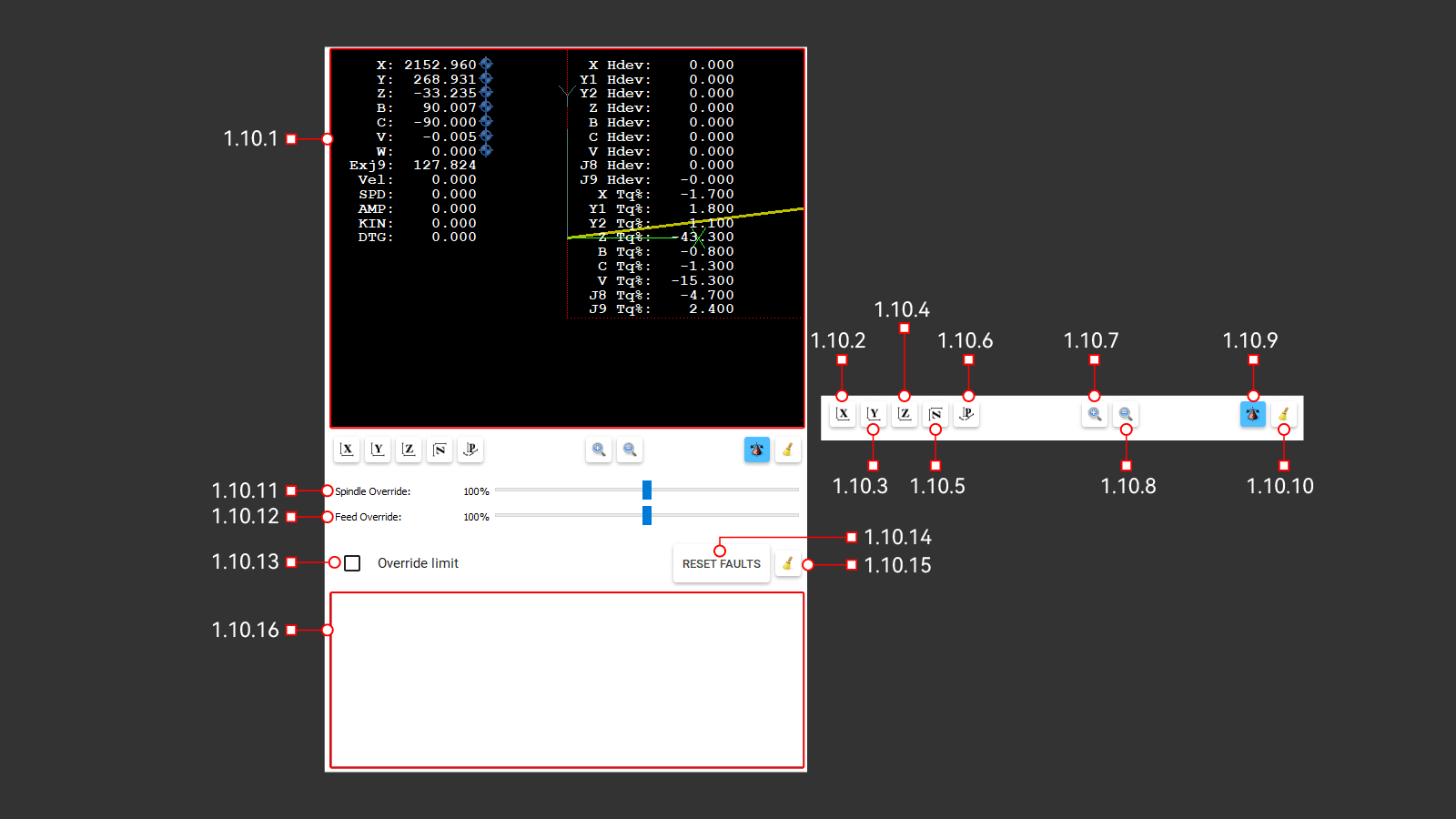
Окно предосмотра визуалиции действий станка и отображение положения стака по осям в реальном времени.
¶ 1.10.1 3D Preview
Окно предосмотра.
¶ 1.10.2 X View
Просмотр загруженной визуализации. Вид паралельно оси X.
¶ 1.10.3 Y View
Просмотр загруженной визуализации. Вид паралельно оси Y.
¶ 1.10.4 Z View
Просмотр загруженной визуализации. Вид паралельно оси Z.
¶ 1.10.5 Z Turned View
Просмотр загруженной визуализации. Параленьно оси Z с поворотом на 90°.
¶ 1.10.6 Orthographic View
Ортогональный вид загруженной визуализации.
¶ 1.10.7 Zoom Out
Увеличение визуализации.
¶ 1.10.8 Zoom In
Уменьшение визуализации.
¶ 1.10.9 Rotation Mode Toggle
Включение функции 3д обзора загруженной визуализации программы в окне просмотра.
¶ 1.10.10 Clean Plot
Очистка предыдущих траекторий перемещения станка в окне предосмотра.
¶ 1.10.11 Spindle Override
Бегунок для переопределения скорости вращения шпинделя от установленного в параметрав в процентном соотношении.
¶ 1.10.12 Feed Override
Бегунок для переопределения скорости резки от установленного в параметрав в процентном соотношении.
¶ 1.10.13 Override Limit
Выключение лимитов, для снятия блокировки перемещения по осям.
¶ 1.10.14 Reset Faults
Кнопка для сброса неисправностей.
¶ 1.10.15 Clean Warnings/Errors
Кнопка для очистки окна сообщения.
¶ 1.10.16 Error List
Окно вывода сообщения о ошибках и отчетов о выполненных командах, а также предупреждения для оператора.
¶ 1.11 Bottom Toolbar
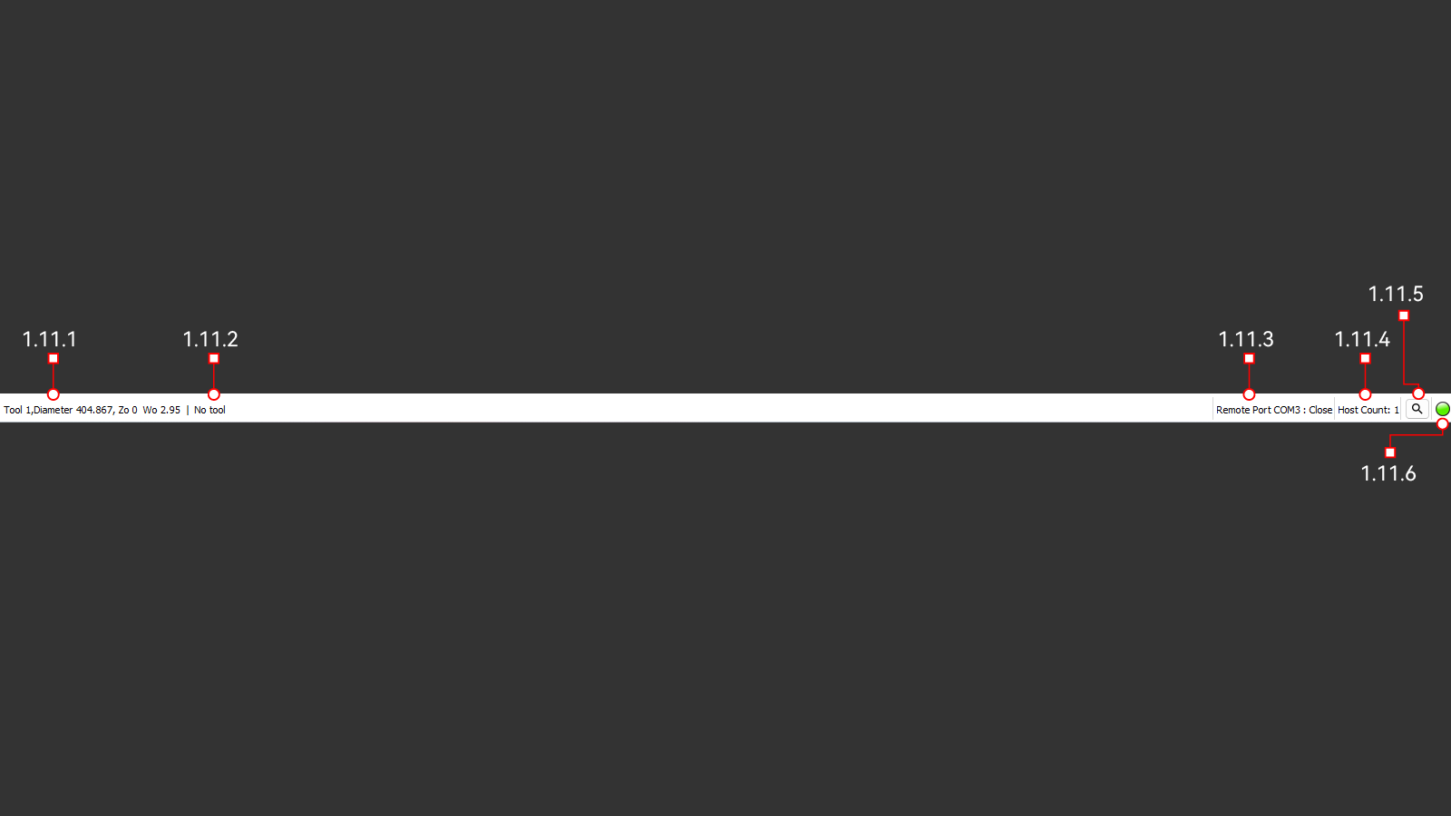
Нижняя строка состояния и информации.
¶ 1.11.1 Main Tool
Основной инструмент.
¶ 1.11.2 Second Tool
Второй дополнительный инструмент.
¶ 1.11.3 Remote Port
Номер порта для подключения пульта дистанционного управления.
¶ 1.11.4 Camera Status
Состояние подключения камеры.
¶ 1.11.5 Search Camera
Сброс и подключение к камере.
¶ 1.11.6 Connectivity Status Light
Сигнал состояния подключения.